More languages
More actions
No edit summary |
No edit summary |
||
| Line 334: | Line 334: | ||
= Data pack download = | = Data pack download = | ||
百度云盘链接:[[File:Zip-001.png|24x24px]] [https://pan.baidu.com/s/1VQMqYcShucpGoCy9Sz1ajg?pwd=c9h7 '''4.3寸ESP32-TN-S3驱动显示模块资料包(提取码:c9h7)'''] | |||
= Product documentation = | = Product documentation = | ||
Revision as of 16:16, 12 May 2026
Product Picture
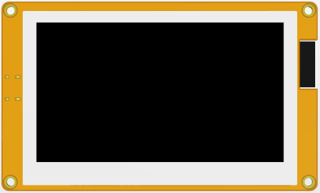
ES3R43P-TopView
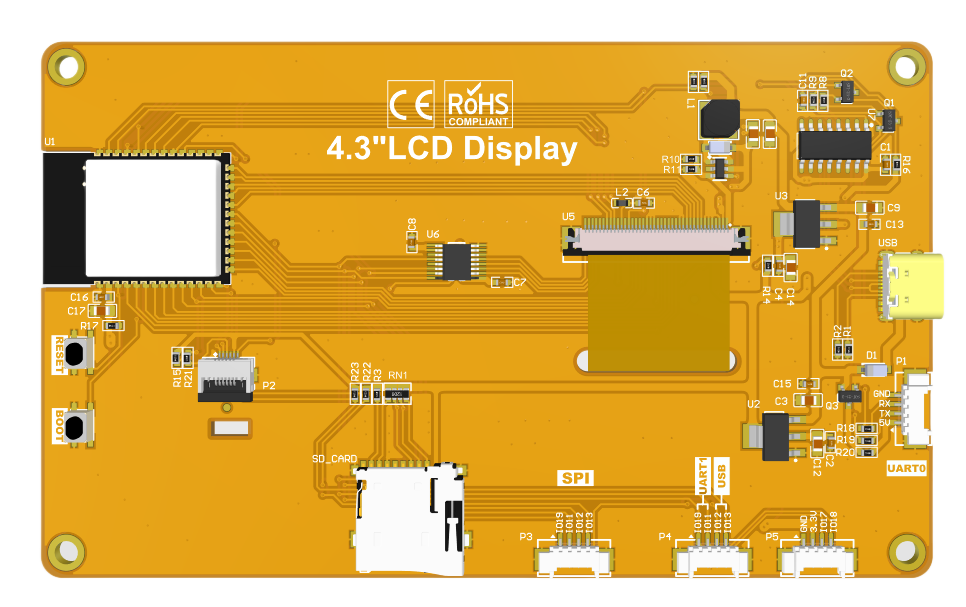
ES3R43P-BottomView


Product Description
- Integrated with ESP32-S3, boasting powerful performance, easy development and abundant development resources.
- 4.3-inch color screen with a resolution of 480x272 and rich display colors (RGB565).
- Rich interfaces for easy connection of various peripherals (IIC, UART, etc.).
- Built-in resistive touch screen for convenient human-computer interaction.
- Standard TYPE-C interface for easy program downloading and power supply.
- Built-in micro TF card slot for convenient storage expansion.
- Abundant sample programs are provided for easy learning.
- Underlying driver technical support is available, with WIKI materials updated online.
- The module has passed multiple aging tests and inspections, meeting military-grade standards and supporting long-term stable operation.
Product Parameters
ESP32 Parameters
| Name | Parameter |
|---|---|
| Module | ESP32-S3 |
| CPU | Xtensa LX7 32-bit dual-core processor |
| Clock rate | 240MHz(MAX) |
| Memory | 384KB ROM+512KB SRAM+16KB RTC SRAM+8M internal OPI PSRAM +16M external SPI Flash
(N16R8) |
| WIFI | 2.4GHz, 802.11b/g/n mode |
| Bluetooth | Bluetooth V5.0 BR/EDR and Bluetooth LE standard |
| Operation voltage | 3.0~3.6(V) |
Screen parameters
| Item | parameters |
|---|---|
| Screen Size | 4.3inch |
| Screen Type | TN |
| Screen resolution | 480xRGBx272(pixels) |
| Active Area | 95.04(W)x53.86(H)(mm) |
| Number of pixels | 65K(RGB565) |
| Drive IC | ST7282 |
| Screen interface | RGB565-16Bit |
| pixels size | 0.153(H)x0.153(mm) |
| View Angle | 6 ’CLOCK |
| Luminance(TYP) | 350 cd/m2 |
| Backlight Type | White LED*7 |
| Operation Temperature | -20~60(℃) |
| Storage Temperature | -30~70(℃) |
Other parameters
| Item | parameters | |
|---|---|---|
| SKU | ES3R43P | ES3N43P |
| Effective area size | 4.3 inch | |
| Operation Temperature | 5.0V | |
| Power interface | USB(Type-C) | |
| Total current(TPY) | 190mA | 190mA |
| Backlight brightness(actual value) | 350cd/m2 | 490cd/m2 |
| Total Power | 0.95W | 0.95W |
| Touch screen type | Resistive touch screen | Not |
| Resolution | 480x272(pixels) | 480x272(pixels) |
| Driver IC | XPT2046 | NOT |
| Communication Interface | SPI | NOT |
| Material | ITO film +ITO glass | NOT |
| LCD Outline Size | 105.50±0.2(W)x67.20±0.2(H)x3.0±0.1(D)(Excluding cables and adhesive backing)(mm) | |
| Touch Screen Outline Size | 105.50±0.2(W)x67.20±0.2(H)x4.2±0.1(D)(Excluding cables and adhesive backing)(mm) | NOT |
| Module Outline Size | 123.00(W)x74.00(H)x8.7(D)(mm) | 123.00(W)x74.00(H)x7.5(D)(mm) |
| Operation Temperature | -20~60(℃) | -20~60(℃) |
| Storage Temperature | -30~70(℃) | -30~70(℃) |
| Weight(including package) | (ES3R43P): g | (ES3N43P): g |
Interface Definition

Interface Function Description
| Interface Name | Function Description |
|---|---|
| ① ESP32-S3 | Display module main control,control board peripheral and external peripheral. |
| ② MicroSD card slot | A MicroSD card is inserted to expand the storage space for storing
large data such as characters, pictures, and audio files. |
| ③ Serial port | 1.25mm 4P connector.It can be used for serial debugging, downloading,
and communication. An external USB to serial port module is required. |
| ④ BOOT Key | Used to enter download mode or key test.
Press and hold this button to power on and release it to enter the download mode. Alternatively, press and hold this button and then press the RESET button to release the RESET button and then release this button to enter the download mode. When you do not need to enter the download mode, this button can be used as a common button. |
| ⑤ Type-C Interface | Used for module power supply and download programs.
This interface is connected to the one-click download circuit on the module, which can automatically enter the download mode (without pressing the BOOT key). |
| ⑥ RESET Key | Used for ESP32 master control and LCD reset, level reset after pressing. |
| ⑦ Expand Pin | 1.25mm 4P socket, leading out GPIO17/GPIO18 pins. |
| ⑧ UART1 & USB | 1.25mm 4P socket, leading out four free pins: GPIO17, GPIO18, GPIO19 and GPIO20. GPIO17 and GPIO18 can be used for UART1, while GPIO19 and GPIO20 are compatible with the USB protocol. |
| ⑨ SPI Interface | 1.25mm 4P socket, designed for connecting external SPI communication devices. This SPI interface is shared with the resistive touch screen and SD card, and can also be used as GPIO. |
ESP32 Pin Assignment
| Onboard Equipment | ESP32 Connect Pins | Pin Description of Onboard Equipment |
|---|---|---|
| LCD | IO40 | Data Enable Control Pin |
| IO41 | Vertical Sync Signal Control Pin | |
| IO39 | Horizontal Sync Signal Control Pin | |
| IO42 | Pixel Clock Control Pin | |
| IO42/48/47/21/14 | 5-bit RED Data Pin | |
| IO5/6/7/15/16/4 | 6-bit GREEN Data Pin | |
| IO8/3/46/9/1 | 5-bit BLUE Data Pin | |
| RTP | IO12 | Resistive Touch Screen SPI Bus Clock Control Pin |
| IO13 | Resistive Touch Screen SPI Bus Data Write Control Pin | |
| IO11 | Resistive Touch Screen SPI Bus Data Read Control Pin | |
| IO38 | Resistive Touch Screen SPI Bus Chip Select Control Pin | |
| IO18 | Resistive Touch Screen SPI Bus Interrupt Control Pin | |
| MicroSD | IO10 | SD Card SPI Bus Chip Select Control Pin |
| IO11 | SD Card SPI Bus Data Read Control Pin | |
| IO13 | SD Card SPI Bus Data Write Control Pin | |
| IO12 | SD Card SPI Bus Clock Control Pin | |
| KEY | IO0 | Download Mode Selection Button (Press this button to power on, then release to enter download mode) |
| EN | ESP32-S3 Reset Button, Active Low Reset | |
| UART0 | RXD0(IO43) | ESP32-S3 UART0 Transmit Signal Pin |
| TXD0(IO44) | ESP32-S3 UART0 Receive Signal Pin | |
| SPI | IO19 | SPI Bus Chip Select Control Pin |
| IO11 | SPI Bus Data Read Control Pin | |
| IO13 | SPI Bus Data Write Control Pin | |
| IO12 | SPI Bus Clock Control Pin | |
| Expand pin | IO18 | It can be used as GPIO when the touch and SD card functions are not in use. |
| IO17 | It can be used as GPIO when the touch and SD card functions are not in use. | |
| USB | IO19 | USB Bus Differential Signal Data Line (Negative) |
| IO20 | USB Bus Differential Signal Data Line (Positive) | |
| UART1 | IO17 | ESP32-S3 UART1 Transmit Signal Pin |
| IO18 | ESP32-S3 UART1 Receive Signal Pin |
Quick usage guide
![]() 4.3inch_ESP32-S3_Quick_Start_Manual
4.3inch_ESP32-S3_Quick_Start_Manual
Data pack download
百度云盘链接:![]() 4.3寸ESP32-TN-S3驱动显示模块资料包(提取码:c9h7)
4.3寸ESP32-TN-S3驱动显示模块资料包(提取码:c9h7)
Product documentation
Specifications
Product Specifications
LCD Specifications
User manual
Size
3D
Hardware schematic diagram
I/O resource allocation table
References
Development environment setup
![]() ESP32 Arduino IDE Development environment setup
ESP32 Arduino IDE Development environment setup
![]() ESP32 MicroPython Development environment setup
ESP32 MicroPython Development environment setup
示例代码说明
![]() 2.8寸ESP32-S3显示模块MicroPython示例程序说明
2.8寸ESP32-S3显示模块MicroPython示例程序说明