Difference between revisions of "1.44inch Arduino SPI Module ST7735S SKU:MAR1441"
(→Interface Definition) |
(→Interface Definition) |
||
| Line 77: | Line 77: | ||
==<font color="blue">Interface Definition</font> == | ==<font color="blue">Interface Definition</font> == | ||
[[file:MAR1441-013.jpg|550x550px]] | [[file:MAR1441-013.jpg|550x550px]] | ||
| + | |||
| + | {| class="wikitable" border="1" style="width: 550px; background-color: white;" | ||
| + | |序号 | ||
| + | | align="center" |引脚标号 | ||
| + | | align="center" |说明 | ||
| + | |- | ||
| + | | align="center" |1 | ||
| + | | align="center" |VCC | ||
| + | |液晶屏电源正(3.3V~5V) | ||
| + | |- | ||
| + | | align="center" |2 | ||
| + | | align="center" |GND | ||
| + | |液晶屏电源地 | ||
| + | |- | ||
| + | | align="center" |3 | ||
| + | | align="center" |GND | ||
| + | |液晶屏电源地 | ||
| + | |- | ||
| + | | align="center" |4 | ||
| + | | align="center" |NC | ||
| + | |无定义,保留 | ||
| + | |- | ||
| + | | align="center" |5 | ||
| + | | align="center" |NC | ||
| + | |无定义,保留 | ||
| + | |- | ||
| + | | align="center" |6 | ||
| + | | align="center" |LED | ||
| + | |背光控制,高电平点亮,如无需控制则接3.3V常亮 | ||
| + | |- | ||
| + | | align="center" |7 | ||
| + | | align="center" |CLK | ||
| + | |液晶屏SPI总线时钟信号 | ||
| + | |- | ||
| + | | align="center" |8 | ||
| + | | align="center" |SDI | ||
| + | |液晶屏SPI总线写数据信号 | ||
| + | |- | ||
| + | | align="center" |9 | ||
| + | | align="center" |RS | ||
| + | |液晶屏寄存器/数据选择信号,低电平:寄存器,高电平:数据 | ||
| + | |- | ||
| + | | align="center" |10 | ||
| + | | align="center" |RST | ||
| + | |液晶屏复位信号,低电平复位 | ||
| + | |- | ||
| + | | align="center" |11 | ||
| + | | align="center" |CS | ||
| + | |液晶屏片选信号,低电平使能 | ||
| + | |- | ||
| + | |} | ||
| + | |||
{| class="wikitable" border="1" style="width: 550px; background-color: white;" | {| class="wikitable" border="1" style="width: 550px; background-color: white;" | ||
|- | |- | ||
Revision as of 10:58, 14 December 2018
Contents
Product Video
Product Picture


Product Description
- 1.44-inch color screen,support 65K color display,display rich colors
- 128X128 resolution, clear display
- Using the SPI serial bus, it only takes a few IOs to illuminate the display
- With SD card slot for convenient function expansion
- Provide underlying libraries and rich sample programs for Arduino, C51, and STM32 platforms
- Military-grade process standards, long-term stable work
- Provide underlying driver technical support
Product Parameters
| Name | Parameter |
| Display Color | 16BIT RGB 65K color |
| SKU | MAR1441 |
| Screen Size | 1.44(inch) |
| Type | TFT |
| Driver IC | ST7735S |
| Resolution | 128*128 (Pixel) |
| Module Interface | 4-wire SPI interface |
| Backlight | 1 White Led |
| Active Area | 26.2x27.2 (mm) |
| Module PCB Size | 31.49x43.95 (mm) |
| Operating Temperature | -10℃~60℃ |
| Storage Temperature | -20℃~70℃ |
| Operating Voltage | 5V/3.3V |
| Power Consumption | About 90mw |
| Product Weight | About 25(g) |
Interface Definition

| 序号 | 引脚标号 | 说明 |
| 1 | VCC | 液晶屏电源正(3.3V~5V) |
| 2 | GND | 液晶屏电源地 |
| 3 | GND | 液晶屏电源地 |
| 4 | NC | 无定义,保留 |
| 5 | NC | 无定义,保留 |
| 6 | LED | 背光控制,高电平点亮,如无需控制则接3.3V常亮 |
| 7 | CLK | 液晶屏SPI总线时钟信号 |
| 8 | SDI | 液晶屏SPI总线写数据信号 |
| 9 | RS | 液晶屏寄存器/数据选择信号,低电平:寄存器,高电平:数据 |
| 10 | RST | 液晶屏复位信号,低电平复位 |
| 11 | CS | 液晶屏片选信号,低电平使能 |
| Number | Pin Label | Pin Description |
| 1 | LCD_RST | LCD bus reset signal, low level reset |
| 2 | LCD_CS | LCD bus chip select signal, low level enable |
| 3 | LCD_RS | LCD bus command / data selection signal,
low level: command, high level: data |
| 4 | LCD_WR | LCD bus write signal |
| 5 | LCD_RD | LCD bus read signal |
| 6 | GND | Power ground |
| 7 | 5V | 5V power input |
| 8 | 3V3 | 3.3V power input, this pin can be disconnected |
| 9 | LCD_D0 | LCD 8-bit data Bit0 |
| 10 | LCD_D1 | LCD 8-bit data Bit1 |
| 11 | LCD_D2 | LCD 8-bit data Bit2 |
| 12 | LCD_D3 | LCD 8-bit data Bit3 |
| 13 | LCD_D4 | LCD 8-bit data Bit4 |
| 14 | LCD_D5 | LCD 8-bit data Bit5 |
| 15 | LCD_D6 | LCD 8-bit data Bit6 |
| 16 | LCD_D7 | LCD 8-bit data Bit7 |
| 17 | SD_SS | SD card SPI bus chip select signal, low level enable |
| 18 | SD_DI | SD card SPI bus MOSI signal |
| 19 | SD_DO | SD card SPI bus MISO signal |
| 20 | SD_SCK | SD card SPI bus clock signal |
Product Documentation
- 2.4 inch Arduino UNO Module User Manual
- 2.4 inch Arduino UNO Module Size Picture
- 2.4 inch TFT Specifications
- Driver IC ILI9341 Data sheet
Connect to Arduino

|

|
|---|---|
| Arduino UNO direct insertion picture | Arduino Mega2560 direct insertion picture |
How to use on Arduino
- Step 1: Download the test program
- Download the Arduino test program from the Program Download column
- For a description of the relevant test procedures, please refer to the test program documentation in the package
- Step 2: Connect the Arduino development board
- Plug the module directly into the Arduino development board ( Do not plug in?)
- After the module is plugged in, power on the Arduino board
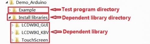
- Step 3: Copy the dependent library
- Make sure the Arduino IDE is installed on your computer (if it is not installed: Arduino IDE download URL)
- After installing the Arduino IDE, you need to copy the dependent library to the Arduino project directory as follows:
- (1) Decompress the downloaded test package
- (2) Copy the dependent libraries in the Install libraries directory in the package (shown below) to the libraries folder
- of the Arduino project directory ( Don't know the Arduino project directory?)

- Step 4: Compile and download the program to the development board
- Open the sample in the Example directory of the package to test, compile and download( Don't know how to compile and download?)
- Step 5: Observe the running of the program
- After the program is downloaded, run it directly and observe the running status. If it can be displayed normally, the program runs
- successfully, as shown in the following figure (take the colligate_test test program as an example):


Program Download
- Demo_Arduino_8BIT
- Demo_STC12C5A60S2_8BIT
- Demo_STM32F103RCT6_8BIT
- Demo_STM32F103ZET6_8BIT
- Demo_STM32F407ZGT6_8BIT
- Demo_STM32F429IGT6_8BIT
Reference Materials
- Arduino IDE software use illustration
- C51 Keil and stc-isp software use illustration
- STM32 keil software use illustration
- PCtoLCD2002 software use illustration
- Image2Lcd software use illustration
- Chinese and English display modulo settings