Difference between revisions of "STM32F407VxT6 Board"
(→Common software) |
|||
| (12 intermediate revisions by 2 users not shown) | |||
| Line 5: | Line 5: | ||
en=http://www.lcdwiki.com/STM32F407VxT6_Board | en=http://www.lcdwiki.com/STM32F407VxT6_Board | ||
}} | }} | ||
| − | |||
| − | |||
| − | |||
==<font color="blue">Product Picture</font> == | ==<font color="blue">Product Picture</font> == | ||
| − | + | [[file:开发板STM32F407VGT6-2.jpg|400px]][[file:开发板STM32F407VGT6-2pin.jpg|400px]][[file:开发板STM32F407VGT6-4pin-2.jpg|400px]] | |
==<font color="blue">Product Features</font> == | ==<font color="blue">Product Features</font> == | ||
| Line 27: | Line 24: | ||
* Provide rich development information | * Provide rich development information | ||
| − | ==<font color="blue"> | + | ==<font color="blue">Hardware Description</font> == |
| − | [[file: | + | [[file:开发板STM32F407VGT6-功能图-2.jpg|800px]] |
{| class="wikitable" border="1" style="width: 800px; background-color: white;" | {| class="wikitable" border="1" style="width: 800px; background-color: white;" | ||
| − | |''' | + | |'''Number''' |
| − | |''' | + | |'''Hardware Name''' |
| − | |''' | + | |'''Description''' |
|- | |- | ||
|① | |① | ||
| − | | | + | |USB communication interface |
| − | | | + | |It is used for USB communication between minimum system board and PC, including USB slave communication (minimum system board as U disk) and USB host (minimum system board as host). This interface can also be used as a power supply interface (except for USB host). |
|- | |- | ||
|② | |② | ||
| − | | | + | |Key0 test button |
| − | | | + | |As a common test button, it can be used for key input function in the program. |
|- | |- | ||
|③ | |③ | ||
| − | | | + | |Reset button |
| − | | | + | |It is used to reset the main chip. In addition, when LCD TFT is directly inserted or FPC flexible cable is used, it can also reset LCD TFT |
|- | |- | ||
|④ | |④ | ||
| − | | | + | |KEY_ Up test/wake up button |
| − | | | + | |Used to wake up the main chip in standby mode. If the wake-up function is not used, it can be used as a normal key input. |
|- | |- | ||
|⑤ | |⑤ | ||
| − | | | + | |SD card slot |
| − | | | + | |It is used to insert SD card and expand the data storage space of the smallest system board. |
|- | |- | ||
|⑥ | |⑥ | ||
|W25Q64 SPI Flash | |W25Q64 SPI Flash | ||
| − | | | + | |It is used to store font, picture and other user data and expand data storage space. |
|- | |- | ||
|⑦ | |⑦ | ||
| − | |3. | + | |3.3V power input / output pin |
| − | | | + | |It is used to provide 3.3V power supply to the external, and it can also connect 3.3V power supply to the minimum system board from the outside. |
|- | |- | ||
|⑧ | |⑧ | ||
| − | | | + | |IO extension |
| − | | | + | |Used to connect external devices. |
|- | |- | ||
|⑨ | |⑨ | ||
| − | |BT0/ | + | |BT0 / BT1 boot select port |
| − | | | + | |It is used to select the startup mode after the main chip is reset. |
|- | |- | ||
|⑩ | |⑩ | ||
| − | | | + | |SWD download simulation interface |
| − | | | + | |It is used to download and simulate the minimum system board. |
|- | |- | ||
|⑪ | |⑪ | ||
| − | | | + | |TFT_ LCD FPC flat cable in line interface |
| − | | | + | |Used to connect LCD module through FPC flexible cable. |
|- | |- | ||
|⑫ | |⑫ | ||
|24C02 EEPROM | |24C02 EEPROM | ||
| − | | | + | |It is used to access some data which can not be lost after power failure, and has less requirements for reading speed and times. |
|- | |- | ||
|⑬ | |⑬ | ||
| − | | | + | |TFT_ LCD pin in line interface |
| − | | | + | |For direct insertion of LCD module through pin array |
|- | |- | ||
|⑭ | |⑭ | ||
| − | |STM32F407VGT6/ | + | |STM32F407VGT6/STM32F407VET6 main chip |
| − | | | + | |Used to execute the program. It has a main frequency of 168mhz, internal SRAM: 192kb, internal flash: 1MB (stm32f407vgt6), 512KB (stm32f407vet6) |
|- | |- | ||
|⑮ | |⑮ | ||
| − | | | + | |LED0 test lamp (blue) |
| − | | | + | |It can be used to test GPIO output, indicate program running status or realize some lighting effects. |
|- | |- | ||
|⑯ | |⑯ | ||
| − | | | + | |LED1 test lamp (blue) |
| − | | | + | |It can be used to test GPIO output, indicate program running status or realize some lighting effects. |
|- | |- | ||
|⑰ | |⑰ | ||
| − | | | + | |Power indicator (red) |
| − | | | + | |Used to indicate the minimum system board power up. |
|- | |- | ||
|⑱ | |⑱ | ||
| − | | | + | |IO extension |
| − | | | + | |Used to connect external devices. |
|- | |- | ||
|⑲ | |⑲ | ||
| − | | | + | |5V power input / output pin |
| − | | | + | |It is used to provide 5V power supply to the external, and can also connect 5V power supply to the minimum system board from the outside. |
|} | |} | ||
| − | ==<font color="blue"> | + | ==<font color="blue">Supported LCD models</font> == |
| + | *2.4inch-MRB2408 | ||
| + | *2.8inch-MRB2801 | ||
| + | *2.8inch-MRB2802 | ||
| + | *3.2inch-MRB3205 | ||
| + | *3.5inch-MRB3503 | ||
| + | *3.5inch-MRB3511 | ||
| + | *3.5inch-MRB3512 | ||
| + | *3.97inch-MRB3973 | ||
| + | *4.0inch-MRB3951 | ||
| + | *4.0inch-MRB3952 | ||
| + | |||
| + | ==<font color="blue">Resource Download</font> == | ||
| − | + | * [http://www.lcdwiki.com/res/Program/Development_Board/STM32/STM32F407VxT6%E6%9C%80%E5%B0%8F%E7%B3%BB%E7%BB%9F%E6%9D%BF%E8%B5%84%E6%96%99%E5%8C%85.zip '''STM32F407VxT6 Minimum system board package'''] | |
| − | * [http://www.lcdwiki.com/res/ | + | * [http://www.lcdwiki.com/res/STM3203/STM32F407VxT6%E6%9C%80%E5%B0%8F%E7%B3%BB%E7%BB%9F%E6%9D%BF%E7%A4%BA%E4%BE%8B%E7%A8%8B%E5%BA%8F.zip '''STM32F407VxT6 Minimum system board sample program'''] |
| − | + | ==<font color="blue">Product Documentation</font> == | |
| − | + | * [http://www.lcdwiki.com/res/STM3203/STM32F407VxT6%E6%9C%80%E5%B0%8F%E7%B3%BB%E7%BB%9F%E6%9D%BF%E4%BD%BF%E7%94%A8%E8%AF%B4%E6%98%8E_V1.0.pdf '''STM32F407VxT6 minimum system board Instructions'''] | |
| + | * [http://www.lcdwiki.com/res/STM3203/STM32F407VxT6_Board_Size.pdf '''STM32F407VxT6 minimum system board size drawing'''] | ||
| + | * [http://www.lcdwiki.com/res/STM3203/STM32F407VxT6_Board_Schematic.pdf '''STM32F407VxT6 minimum system board schematic'''] | ||
| + | * [http://www.lcdwiki.com/res/STM3203/STM32F407VxT6%E6%9C%80%E5%B0%8F%E7%B3%BB%E7%BB%9F%E6%9D%BFIO%E8%B5%84%E6%BA%90%E5%88%86%E9%85%8D%E8%A1%A8.xlsx '''STM32F407VxT6 minimum system board IO resource allocation table'''] | ||
| + | * [http://www.lcdwiki.com/res/STM3203/SCHLIB.zip '''STM32F407VxT6 minimum system board schematic library'''] | ||
| + | * [http://www.lcdwiki.com/res/STM3203/PCBLIB.zip '''STM32F407VxT6 minimum system board PCB package library'''] | ||
| + | * [http://www.lcdwiki.com/res/STM3203/STM32F407%E6%95%B0%E6%8D%AE%E6%89%8B%E5%86%8C.pdf '''STM32F407 data sheet'''] | ||
| + | * [http://www.lcdwiki.com/res/STM3203/STM32F4xx%E8%8B%B1%E6%96%87%E5%8F%82%E8%80%83%E6%89%8B%E5%86%8C.pdf '''STM32F407 English reference manual'''] | ||
| − | + | ==<font color="blue">Reference Material</font> == | |
| − | |||
| − | |||
| − | |||
| − | |||
| − | |||
| − | |||
| − | |||
| − | + | * [http://www.lcdwiki.com/res/STM3203/SWD仿真与调试说明.pdf '''STM32 development board SWD package and debugging download instructions'''] | |
| + | * [http://www.lcdwiki.com/res/STM3203/SWD下载说明.pdf '''STM32 development board SWD download instructions'''] | ||
| + | * [http://www.lcdwiki.com/res/STM3203/串口下载说明.pdf '''STM32 development board serial port download instructions'''] | ||
| − | + | ==<font color="blue">Common software</font> == | |
| − | |||
| − | |||
| − | + | * [http://www.lcdwiki.com/res/software/FLYMCU.zip '''Serial port download software'''] | |
| + | * [http://www.lcdwiki.com/res/software/XCOM.zip '''Serial port Operator software'''] | ||
| + | * [http://www.lcdwiki.com/res/software/PCtoLCD2002.zip '''PCtoLCD2002'''] | ||
| + | * [http://www.lcdwiki.com/res/software/Image2Lcd.zip '''Image2Lcd'''] | ||
| − | |||
| − | |||
[[#top|BACK TO TOP]] | [[#top|BACK TO TOP]] | ||
Latest revision as of 15:44, 3 September 2021
Contents
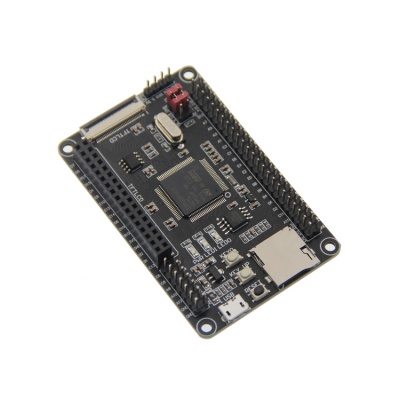
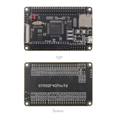
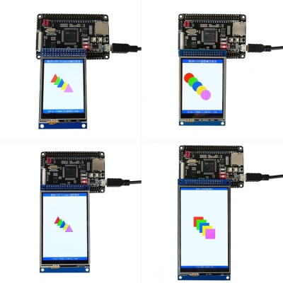
Product Picture
Product Features
- Small and exquisite appearance, convenient for various DIY projects
- Compatible with two CPUs: STM32F407VGT6 and STM32F407VET6
- The main frequency of CPU is as high as 168mhz, which is fast and powerful
- Rich storage resources, with internal SRAM: 192kb, internal flash: 1MB (STM32F407VGT6), 512KB (STM32F407VET6), external SPI flash: 8MB, external EEPROM: 256b
- The SD card can expand the storage space
- Support LCD pin insertion and FPC flexible cable connection
- Support using FSMC bus to drive LCD, fast display speed
- Support SWD and serial port download, easy debugging
- Support USB communication
- Expand the GPIO port to connect various peripherals conveniently
- Development resources are rich, easy to learn, easy to start
- Provide rich development information
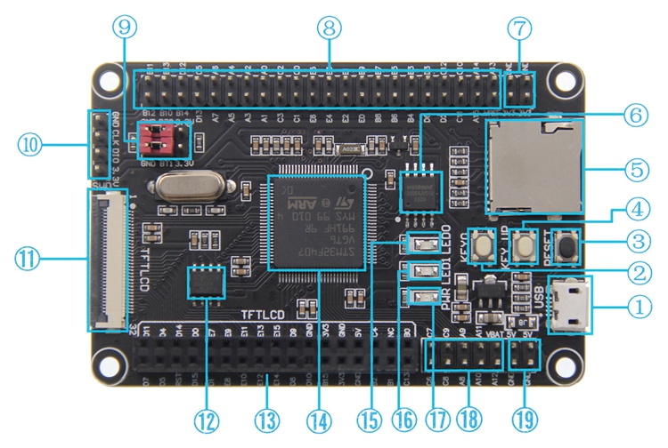
Hardware Description
| Number | Hardware Name | Description |
| ① | USB communication interface | It is used for USB communication between minimum system board and PC, including USB slave communication (minimum system board as U disk) and USB host (minimum system board as host). This interface can also be used as a power supply interface (except for USB host). |
| ② | Key0 test button | As a common test button, it can be used for key input function in the program. |
| ③ | Reset button | It is used to reset the main chip. In addition, when LCD TFT is directly inserted or FPC flexible cable is used, it can also reset LCD TFT |
| ④ | KEY_ Up test/wake up button | Used to wake up the main chip in standby mode. If the wake-up function is not used, it can be used as a normal key input. |
| ⑤ | SD card slot | It is used to insert SD card and expand the data storage space of the smallest system board. |
| ⑥ | W25Q64 SPI Flash | It is used to store font, picture and other user data and expand data storage space. |
| ⑦ | 3.3V power input / output pin | It is used to provide 3.3V power supply to the external, and it can also connect 3.3V power supply to the minimum system board from the outside. |
| ⑧ | IO extension | Used to connect external devices. |
| ⑨ | BT0 / BT1 boot select port | It is used to select the startup mode after the main chip is reset. |
| ⑩ | SWD download simulation interface | It is used to download and simulate the minimum system board. |
| ⑪ | TFT_ LCD FPC flat cable in line interface | Used to connect LCD module through FPC flexible cable. |
| ⑫ | 24C02 EEPROM | It is used to access some data which can not be lost after power failure, and has less requirements for reading speed and times. |
| ⑬ | TFT_ LCD pin in line interface | For direct insertion of LCD module through pin array |
| ⑭ | STM32F407VGT6/STM32F407VET6 main chip | Used to execute the program. It has a main frequency of 168mhz, internal SRAM: 192kb, internal flash: 1MB (stm32f407vgt6), 512KB (stm32f407vet6) |
| ⑮ | LED0 test lamp (blue) | It can be used to test GPIO output, indicate program running status or realize some lighting effects. |
| ⑯ | LED1 test lamp (blue) | It can be used to test GPIO output, indicate program running status or realize some lighting effects. |
| ⑰ | Power indicator (red) | Used to indicate the minimum system board power up. |
| ⑱ | IO extension | Used to connect external devices. |
| ⑲ | 5V power input / output pin | It is used to provide 5V power supply to the external, and can also connect 5V power supply to the minimum system board from the outside. |
Supported LCD models
- 2.4inch-MRB2408
- 2.8inch-MRB2801
- 2.8inch-MRB2802
- 3.2inch-MRB3205
- 3.5inch-MRB3503
- 3.5inch-MRB3511
- 3.5inch-MRB3512
- 3.97inch-MRB3973
- 4.0inch-MRB3951
- 4.0inch-MRB3952
Resource Download
Product Documentation
- STM32F407VxT6 minimum system board Instructions
- STM32F407VxT6 minimum system board size drawing
- STM32F407VxT6 minimum system board schematic
- STM32F407VxT6 minimum system board IO resource allocation table
- STM32F407VxT6 minimum system board schematic library
- STM32F407VxT6 minimum system board PCB package library
- STM32F407 data sheet
- STM32F407 English reference manual
Reference Material
- STM32 development board SWD package and debugging download instructions
- STM32 development board SWD download instructions
- STM32 development board serial port download instructions


