Difference between revisions of "3.95inch Arduino Display-Mega2560"
(→Interface Definition) |
(→Interface Definition) (Tag: Visual edit) |
||
| Line 97: | Line 97: | ||
| align="center" |3 | | align="center" |3 | ||
| align="center" |DB8 | | align="center" |DB8 | ||
| − | |8th bit of data bus | + | |8th bit of data bus(No need to use when using 8-bit mode) |
| align="center" |4 | | align="center" |4 | ||
| align="center" |DB9 | | align="center" |DB9 | ||
| − | |9th bit of data bus | + | |9th bit of data bus(No need to use when using 8-bit mode) |
|- | |- | ||
| align="center" |5 | | align="center" |5 | ||
| align="center" |DB10 | | align="center" |DB10 | ||
| − | |10th bit of data bus | + | |10th bit of data bus(No need to use when using 8-bit mode) |
| align="center" |6 | | align="center" |6 | ||
| align="center" |DB11 | | align="center" |DB11 | ||
| − | |11th bit of data bus | + | |11th bit of data bus(No need to use when using 8-bit mode) |
|- | |- | ||
| align="center" |7 | | align="center" |7 | ||
| align="center" |DB12 | | align="center" |DB12 | ||
| − | |12th bit of data bus | + | |12th bit of data bus(No need to use when using 8-bit mode) |
| align="center" |8 | | align="center" |8 | ||
| align="center" |DB13 | | align="center" |DB13 | ||
| − | |13th bit of data bus | + | |13th bit of data bus(No need to use when using 8-bit mode) |
|- | |- | ||
| align="center" |9 | | align="center" |9 | ||
| align="center" |DB14 | | align="center" |DB14 | ||
| − | |14th bit of data bus | + | |14th bit of data bus(No need to use when using 8-bit mode) |
| align="center" |10 | | align="center" |10 | ||
| align="center" |DB15 | | align="center" |DB15 | ||
| − | |15th bit of data bus | + | |15th bit of data bus(No need to use when using 8-bit mode) |
|- | |- | ||
| align="center" |11 | | align="center" |11 | ||
| − | | align="center" |DB7 | + | | align="center" |DB7 |
| − | |7th bit of data bus | + | |7th bit of data bus |
| align="center" |12 | | align="center" |12 | ||
| − | | align="center" |DB6 | + | | align="center" |DB6 |
| − | |6th bit of data bus | + | |6th bit of data bus |
|- | |- | ||
| align="center" |13 | | align="center" |13 | ||
| − | | align="center" |DB5 | + | | align="center" |DB5 |
| − | |5th bit of data bus | + | |5th bit of data bus |
| align="center" |14 | | align="center" |14 | ||
| − | | align="center" |DB4 | + | | align="center" |DB4 |
| − | |4th bit of data bus | + | |4th bit of data bus |
|- | |- | ||
| align="center" |15 | | align="center" |15 | ||
| − | | align="center" |DB3 | + | | align="center" |DB3 |
| − | |third bit of data bus | + | |third bit of data bus |
| align="center" |16 | | align="center" |16 | ||
| − | | align="center" |DB2 | + | | align="center" |DB2 |
| − | |2nd bit of data bus | + | |2nd bit of data bus |
|- | |- | ||
| align="center" |17 | | align="center" |17 | ||
| − | | align="center" |DB1 | + | | align="center" |DB1 |
| − | |1st bit of data bus | + | |1st bit of data bus |
| align="center" |18 | | align="center" |18 | ||
| − | | align="center" |DB0 | + | | align="center" |DB0 |
| − | |0 bit of data bus | + | |0 bit of data bus |
|- | |- | ||
| align="center" |19 | | align="center" |19 | ||
Revision as of 15:50, 29 March 2019
Contents
Product Video
Product Picture
Product Description
- Support Arduino Mage2560 direct plug-in use
- 3.95-inch color screen, support 16BIT RGB 65K color display, display rich colors
- 320x480 resolution for clear display
- Supports 8-bit and 16-bit parallel bus transmission with fast transfer speed
- On-board 5V/3.3V level shifting IC, compatible with 5V/3.3V operating voltage
- Support touch function
- Provides an Arduino library with a rich sample program
- Available on C51 and STM32 platforms with a rich sample program
- Easy to expand the experiment with SD card slot
- Military-grade process standards, long-term stable work
- Provide underlying driver technical support
Product Parameters
| Name | Parameter |
| Display Color | RGB 65K color |
| SKU | MAR3953 |
| Screen Size | 3.95(inch) |
| Type | TFT |
| Driver IC | ST7796S |
| Resolution | 480*320 (Pixel) |
| Module Interface | 8Bit or 16Bit parallel interface |
| Active Area | 83.52x55.68(mm) |
| Module PCB Size | 61.54x105.69 (mm) |
| back light | 6 chip HighLight white LEDs |
| Operating Temperature | -10℃~60℃ |
| Storage Temperature | -20℃~70℃ |
| Operating Voltage | 5V/3.3V |
| Power Consumption | TBD |
| Product Weight | TBD |
Interface Definition
| Number | Module Pin | Pin Description | Number | Module Pin | Pin Description |
|---|---|---|---|---|---|
| 1 | 5V | Positive power supply | 2 | 5V | Positive power supply |
| 3 | DB8 | 8th bit of data bus(No need to use when using 8-bit mode) | 4 | DB9 | 9th bit of data bus(No need to use when using 8-bit mode) |
| 5 | DB10 | 10th bit of data bus(No need to use when using 8-bit mode) | 6 | DB11 | 11th bit of data bus(No need to use when using 8-bit mode) |
| 7 | DB12 | 12th bit of data bus(No need to use when using 8-bit mode) | 8 | DB13 | 13th bit of data bus(No need to use when using 8-bit mode) |
| 9 | DB14 | 14th bit of data bus(No need to use when using 8-bit mode) | 10 | DB15 | 15th bit of data bus(No need to use when using 8-bit mode) |
| 11 | DB7 | 7th bit of data bus | 12 | DB6 | 6th bit of data bus |
| 13 | DB5 | 5th bit of data bus | 14 | DB4 | 4th bit of data bus |
| 15 | DB3 | third bit of data bus | 16 | DB2 | 2nd bit of data bus |
| 17 | DB1 | 1st bit of data bus | 18 | DB0 | 0 bit of data bus |
| 19 | LCD_RS | LCD register / data selection signal
Low level: register, high level: command |
20 | LCD_WR | LCD write control signal |
| 21 | LCD_CS | LCD screen select control signal, low level enable | 22 | LCD_RST | LCD reset control signal, low reset |
| 23 | NC | Undefined, reserved | 24 | LCD_RD | LCD read control signal |
| 25 | TP_IRQ | Touch screen interrupt control signal, low level when touch is detected | 26 | NC | Undefined, reserved |
| 27 | NC | Undefined, reserved | 28 | NC | Undefined, reserved |
| 29 | SD_CS | SD card select control signal, low level enable | 30 | NC | Undefined, reserved |
| 31 | MISO | SPI bus input signal | 32 | MOSI | Touch screen chip select control signal, low level enable |
| 33 | EX_CLK | SPI bus clock signal | 34 | TP_CS | SD card select control signal, low level enable |
| 35 | GND | Power ground | 36 | GND | Power ground |
Product Documentation
- 3.8 inch Arduino Mega2560 Module User Manual
- 3.8 inch Arduino Mega2560 Module Size Picture
- Driver IC ILI9486 Data sheet
Connect to Arduino

|
|---|
| Arduino Mega2560 direct insertion picture |
How to use on Arduino
- Step 1: Download the test program
- Download the Arduino test program from the Program Download column
- For a description of the relevant test procedures, please refer to the test program documentation in the package
- Step 2: Connect the Arduino development board
- Plug the module directly into the Arduino development board ( Do not plug in?)
- After the module is plugged in, power on the Arduino board
- Step 3: Copy the dependent library
- Make sure the Arduino IDE is installed on your computer (if it is not installed: Arduino IDE download URL)
- After installing the Arduino IDE, you need to copy the dependent library to the Arduino project directory as follows:
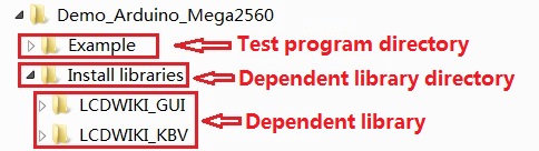
- (1) Decompress the downloaded test package
- (2) Copy the dependent libraries in the Install libraries directory in the package (shown below) to the libraries folder
- of the Arduino project directory ( Don't know the Arduino project directory?)

- Step 4: Compile and download the program to the development board
- Open the sample in the Example directory of the package to test, compile and download( Don't know how to compile and download?)
- Step 5: Observe the running of the program
- After the program is downloaded, run it directly and observe the running status. If it can be displayed normally, the program runs
- successfully, as shown in the following figure (take the colligate_test test program as an example):


Program Download
Reference Materials
- Arduino IDE software use illustration
- C51 Keil and stc-isp software use illustration
- STM32 keil software use illustration
- PCtoLCD2002 software use illustration
- Image2Lcd software use illustration
- Chinese and English display modulo settings