More actions
| Line 319: | Line 319: | ||
both 8-bit and 16-bit modes),the modification method is as follows: | both 8-bit and 16-bit modes),the modification method is as follows: | ||
Open the file | Open the file '''LCDWKI_KBV\lcd_mode.h''' and set the '''CONFIG_USE_8BIT_BUS''' macro to 1, as shown below: | ||
{{code|1= | {{code|1= | ||
Revision as of 10:37, 30 June 2018
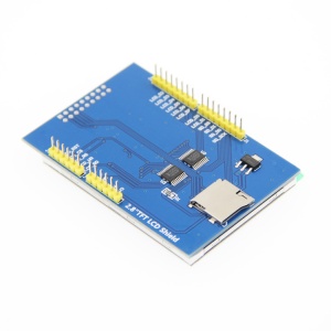
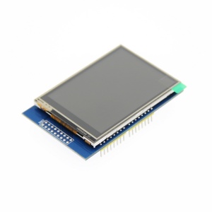
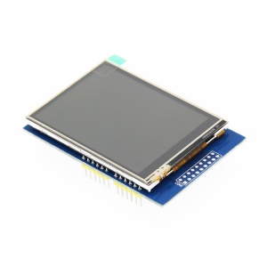
Product picture
Product description
- Support development boards such as ArduinoUNO and Mega2560 for use without wiring
- 320X240 HD resolution and support touch function
- Supports 16-bit RGB 65K color display and rich color display
- using 8-bit parallel bus, refresh faster than serial SPI
- With SD card slot to facilitate the expansion of the experiment
- Provide Arduino library, provide a wealth of sample programs
- Military-grade process standards, long-term work stably
- Provides underlying driver technology support
- Data Acquisition: See Driver download
Product parameters
| name | parameter |
| SKU | MAR2808 |
| size | 2.8(inch) |
| type | TFT |
| driver chip | ILI9341 |
| resolution | 320*240 (Pixel) |
| module interface | 8-bit parallel interface |
| effective display area | 57.6x43.2(mm) |
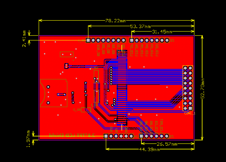
| module PCB size | 78.22x52.7(mm) |
| operating temperature | -20℃~70℃ |
| operating Voltage | 5V |
| power consumption | about 90mw |
| product weight | 25(g) |
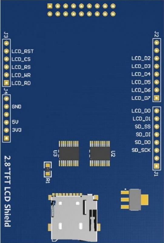
Interface definition
| number | label | pin description |
| 1 | LCD_RST | LCD bus reset signal |
| 2 | LCD_CS | LCD bus chip select signal |
| 3 | LCD_RS | LCD bus command/data select signal |
| 4 | LCD_WR | LCD bus write signal |
| 5 | LCD_RD | LCD bus read signal |
| 6 | GND | power ground |
| 7 | 5V | 5V power input |
| 8 | 3V3 | NC this pin can not be connected |
| 9 | LCD_D0 | LCD 8-bit data Bit0 |
| 10 | LCD_D1 | LCD 8-bit data Bit1 |
| 11 | LCD_D2 | LCD 8-bit data Bit2 |
| 12 | LCD_D3 | LCD 8-bit data Bit3 |
| 13 | LCD_D4 | LCD 8-bit data Bit4 |
| 14 | LCD_D5 | LCD 8-bit data Bit5 |
| 15 | LCD_D6 | LCD 8-bit data Bit6 |
| 16 | LCD_D7 | LCD 8-bit data Bit7 |
| 17 | SD_SS | SD card SPI bus chip select signal |
| 18 | SD_DI | SD card SPI bus MOSI signal |
| 19 | SD_DO | SD card SPI bus MISO signal |
| 20 | SD_SCK | SD card SPI bus clock signal |
Product size
Product size drawing:
Hardware description
Hardware schematic:Arduino 2.8 inch display module schematic.pdf
Using Instructions
Arduino platform using instructions
1.Wiring instructions
| connect with UNO development board | Connect with Mega2560 Development Board | ||
|---|---|---|---|
| pins on the module | UNO microcontroller pin | pins on the module | Mega2560 microcontroller pin |
| LCD_RST | A4 | LCD_RST | 5V |
| LCD_CS | A3 | LCD_CS | GND |
| LCD_RS | A2 | LCD_RS | 21 |
| LCD_WR | A1 | LCD_WR | 20 |
| LCD_RD | A0 | LCD_RD | A0 |
| GND | GND | GND | GND |
| 5V | 5V | 5V | 5V |
| LCD_D0 | 8 | LCD_D0 | 8 |
| LCD_D1 | 9 | LCD_D1 | 9 |
| LCD_D2 | 2 | LCD_D2 | 2 |
| LCD_D3 | 3 | LCD_D3 | 3 |
| LCD_D4 | 4 | LCD_D4 | 4 |
| LCD_D5 | 5 | LCD_D5 | 5 |
| LCD_D6 | 6 | LCD_D6 | 6 |
| LCD_D7 | 7 | LCD_D7 | 7 |
| SD_SS | 10 | SD_SS | 10 |
| SD_DI | 11 | SD_DI | 11 |
| SD_DO | 12 | SD_DO | 12 |
| SD_SCK | 13 | SD_SCK | 13 |
2.operating instructions
a.Connect the 2.8-inch display module to the Arduino development board according to the wiring instructions and power it on (note the development board model)
b.Download the 2.8 inch display module package from Drive download column
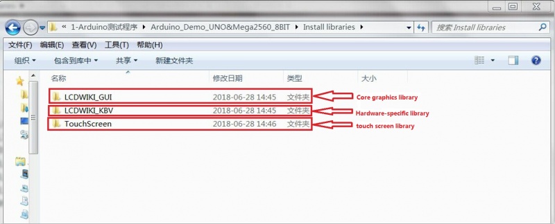
c.Extract the data package,open the install library folder,you can see the LCDWIKI_GUI,LCDWIKI_KBV and touch screen these three libraries,as shown below:
d.Copy the three libraries:LCDWIKI_GUI,LCDWIKI_KBV,and touch screen to the directory where the Arduino project files are located,
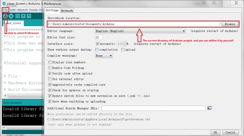
The default directory for Arduino project files is "C:\Users\Administrator\Documents\Arduino",You can define it yourself as follows:
Open Arduino IDE software,click File->Preferences to define the directory where Arduino project files are located,as shown in the following figure:
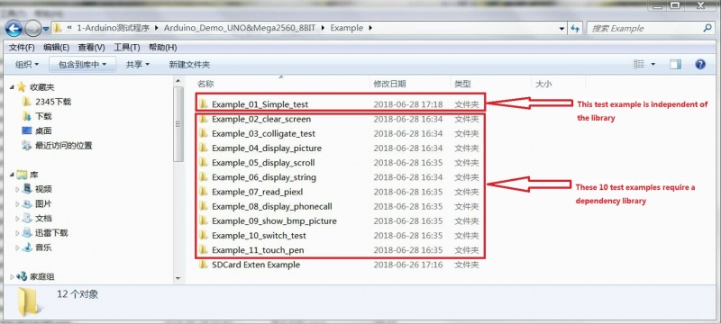
e.Open the Example folder in the package, you can see there are 11 test examples, as shown below:
f.Open any test example,eg open "Example_02_clear_screen"
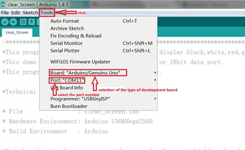
g.After opening the "Example_02_clear_screen" test program,click the Tools button to select the board model and port number,as shown in the following figure:
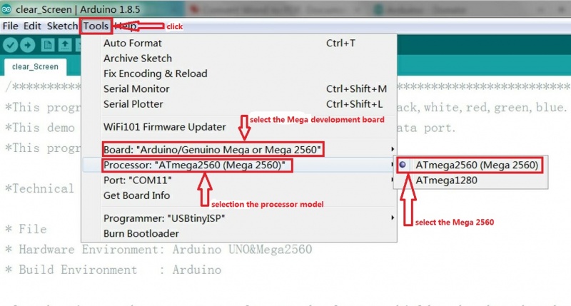
If the development board model selection Mega, you also need to select the processor model, for the 2.8-inch display module,
we only select the ATmega2560 processor, as shown below:
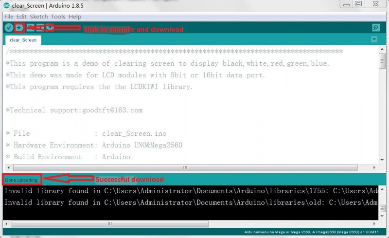
h.Click the upload button to compile and download. When "Done Uploading" is displayed,the program has been successfully downloaded to the development board,
as shown in the following figure:
i.If the 2.8-inch display module is continuously displayed in black, white, red, green, and blue, the program runs successfully.
precautions
a.The display module uses 8-bit parallel port to transfer data,so the LCDWIKI library also needs to be set to 8-bit mode (since the LCDWIKI library supports
both 8-bit and 16-bit modes),the modification method is as follows:
Open the file LCDWKI_KBV\lcd_mode.h and set the CONFIG_USE_8BIT_BUS macro to 1, as shown below:
//if using 8bit mode,set the below macro definition to 1
//if using 16bit mode,set the below macro definition to 0
#define CONFIG_USE_8BIT_BUS 1

