
More actions
No edit summary |
No edit summary |
||
| Line 278: | Line 278: | ||
|SD card SPI bus read data signal | |SD card SPI bus read data signal | ||
|- | |- | ||
| align="center" |''' | | align="center" |'''Audio''' | ||
| align="center" |IO26 | | align="center" |IO26 | ||
|Audio output signal | |Audio output signal | ||
Revision as of 18:25, 28 August 2026
Product Picture
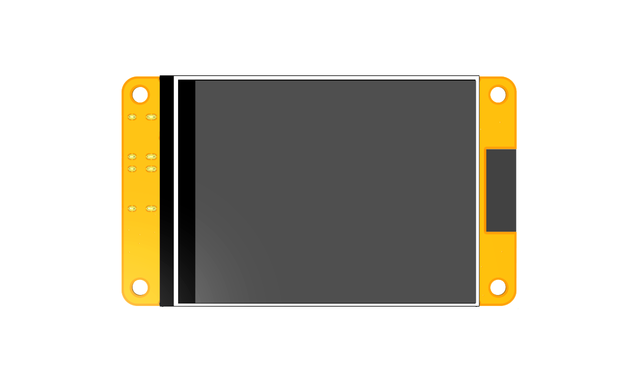
TopView
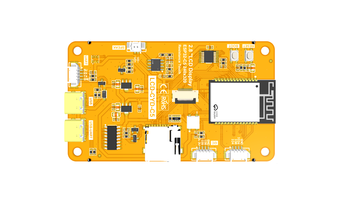
BottomView


Product Description
- Built-in ESP32‑C5 module for convenient development with abundant resources
- 2.8-inch color LCD, 240×320 resolution, max. 262K colors (RGB666), rich color performance
- Rich interfaces for connecting SPI, UART and other peripherals
- On-board RGB tri-color indicator LED for multi-status indication
- On-board resistive touch-screen for human-machine interaction
- Standard Type-C connector for power supply & firmware download
- On-board Micro-TF card slot for storage expansion
- Rich sample codes provided for quick evaluation
- Underlying driver technical support and continuously-updated WIKI documents
- Multi-stress aging test for stable long-term operation
Product Parameters
ESP32 Parameters
| Name | Parameter |
|---|---|
| Module | ESP32-C5-WROOM-1-N16R8 |
| CPU | RISC-V 32-bit single-core processor |
| Frequency | 240MHz(Max) |
| Memory | 320KB ROM + 384KB HP-SRAM + 16KB LP-SRAM + 16MB QSPI Flash + 8MB PSRAM |
| WIFI | 2.4GHz & 5GHz dual-band Wi-Fi 6 802.11ax, backward compatible with 802.11a/b/g/n/ac |
| Bluetooth | Bluetooth 6.0 LE, supports Bluetooth Mesh 1.1; compatible with IEEE802.15.4 (Zigbee3.0 / Thread1.4) |
| Operating Voltage | 3.0~3.6(V) |
LCD Parameters
| Name | Parameter |
|---|---|
| Panel Size | 2.8 inch |
| Panel Type | TN TFT |
| Resolution | 240xRGBx320(pixels) |
| Active Area | 43.20(W)x57.60(H) |
| Number of Colors | Max: 262K(RGB666)
Common: 65K(RGB565) |
| Driver IC | ST7789P3 |
| Display Interface | 4-Line SPI(Connect to ESP32) |
| Pixel Size | 0.153(H)x0.153(mm) |
| View Angle | 12 0’CLOCK |
| Brightness(TYP) | 400 cd/m2 |
| Backlight Type | White LED*4 |
| Operation Temperature | -10~50(℃) |
| Storage Temperature | -20~60(℃) |
Touch Screen Parameters
| Name | Parameter |
|---|---|
| Touch Active Area | 2.8 inch |
| Touch Screen Type | Resistive touch screen |
| Touch Screen Resolution | 240x320(pixels) |
| Driver IC | XPT2046 |
| Touch Screen Visual Area | 45.20(W)x59.45(H)(mm) |
| Communication Interface | SPI |
| Material | ITO film +ITO glass |
| Operation Temperature | -20~60(℃) |
| Storage Temperature | -30~70(℃) |
Size Parameters
| Name | Parameter |
|---|---|
| LCD Outline Size | 50.00±0.2(W)x69.20±0.2(H)x2.3±0.1(D)(mm)
(Excluding cables and adhesive backing) |
| Touch Screen Outline Size | 49.60±0.2(W)x68.80±0.2(H)x1.20 (D)(mm)
(Excluding cables and adhesive backing) |
| Module Outline Size | 50.00(W) x 86.00(H) x 5.60(D)(mm) |
Electrical Parameters
| Name | Parameter |
|---|---|
| Working Voltage | 5.0V |
| Backlight Current | |
| Total Current | |
| Power |
Basic Parameters
| Name | Parameter |
|---|---|
| SKU | |
| Power Supply Interface | TYPE-C |
| Weight(including package) |
Interface Definition

Interface Function Description
| Interface Name | Function Description |
|---|---|
| ESP32-C5 Module | Display module main control,control board peripheral and external peripheral. |
| TF Slot | Insert a Micro SD card to expand storage space, e.g., for storing fonts, images, and other large data content. |
| RGB LED | Contains red, green, and blue LEDs, each controllable via I/O pins for status indication. |
| LP_UART | 1.25mm 4P connector. Can be used for serial debugging, downloading, and communication. Requires an external USB-to-serial module. |
| BOOT Button | Used to enter download mode or for button testing. Hold this button during power-on and release to enter download mode. Alternatively, after power-on, hold this button, press the RESET button, release RESET first, then release this button to enter download mode. When not used for download mode, this button can serve as a regular button. |
| RESET Button | Used for ESP32 MCU and LCD reset. Pressing it triggers a level reset. |
| USB Interface | Used for module power supply and program download. This interface is connected to the ESP32-S3 internal USB bus and can create a USB virtual serial port. |
| USB-UART Interface | Used for module power supply and program download. This interface is connected to the one-key download circuit on the module, enabling automatic entry into download mode (no need to press the BOOT button). |
| Extended Pins | 1.25mm 4P connector. Brings out GND, IO26, IO8, and IO4 pins. |
| Speaker Interface | 1.25mm 2P connector. Used for connecting a speaker to play audio or for motor driving (Note: since the C5 has no DAC, audio playback quality is relatively poor). |
| I2C Peripheral Interface | 1.25mm 4P connector. Used for connecting external I2C communication devices. |
ESP32 Pin Assignment
| Onboard Equipment | ESP32 Connect Pins | Pin Description of Onboard Equipment |
|---|---|---|
| LCD | IO23 | LCD screen selection control signal, low level effective |
| IO24 | LCD command/data selection control signal
High Level:data,low Level:command | |
| IO6 | LCD SPI bus clock signal | |
| IO7 | LCD SPI bus write data signal | |
| IO2 | LCD SPI bus read data signal | |
| EN | LCD reset control signal, low level reset(share reset pin with ESP32-C5 master) | |
| IO25 | LCD backlight control signal(high level backlight on, low level backlight off) | |
| Resistive Touch Screen | IO6 | Resistive touch screen SPI bus clock signal |
| IO2 | Resistive touch screen SPI bus write data signal | |
| IO7 | Resistive touch screen SPI bus read data signal | |
| IO1 | Resistive touch screen chip selection control signal,low level effective | |
| IO3 | Resistive touch screen touch interrupt signal,
generates touch when input low level to master | |
| SDCARD | IO10 | SD card chip select control signal, active low |
| IO2 | SD card SPI bus write data signal | |
| IO6 | SD card SPI bus clock signal | |
| IO7 | SD card SPI bus read data signal | |
| Audio | IO26 | Audio output signal |
| KEY | IO28 | Download mode selection button (hold during power-on, then release to enter download mode) |
| EN | ESP32-C5 reset button, active low reset (shared with LCD reset) | |
| Serial Port | RXD0(IO12) | ESP32-C5 UART0 receive signal interface |
| TXD0(IO11) | ESP32-C5 UART0 transmit signal interface | |
| RGB LED | IO27 | Single-wire RGB tri-color LED; independently controls red, green, and blue LEDs via |
| LP_Serial | IO4 | Extended external LP_UART receive signal interface |
| IO5 | Extended external LP_UART transmit signal interface | |
| IIC | IO8 | Extended external I2C data signal interface |
| IO9 | Extended external I2C clock signal interface |
Quick Start Instructions
 2.8-inch ESP32-C5 display module Quick_Start Package
 2.8-inch ESP32-C5 display module Qucik Start
Data Pack Download
Download Path 1 (Google Drive Download)
2.8寸ESP32-C5-ST7789 LCD Module Data package(Google Drive Download)
Download Path 2 (Baidu Cloud Disk)
2.8寸ESP32-C5-ST7789 LCD Module Data package(Extract code:4e3r)
Product Documentation
Specification
Product Specification
 2.8-inch ESP32-C5 display module Specification
LCD Specifications
2.8-inch QD2803 screen specification
User Manual
2.8-inch ESP32-C5 display module User Manual
Dimension Drawing
E32R28T display module dimensions
E32N28T display module dimensions
3D Drawing
E32R28T display module 3D image
E32N28T display module 3D image
Schematic
2.8-inch ESP32-C5 display module Schematic diagram
IO Resource Allocation Table
 ESP32 IO resource allocation table
Package Library
2.8-inch ESP32-C5 display module AD package library
LCD Initialization Code

Reference Materials
Development environment construction
Arduino IDE1 development environment construction for ESP32
Arduino IDE2 development environment construction for ESP32
MicroPython development environment construction for ESP32
ESP-IDF using VSCODE development environment construction for ESP32
ESP-IDF LVGL porting construction for ESP32
Demo Instructions
2.8-inch ESP32-C5 display module Arduino Demo Instructions
2.8-inch ESP32-C5 display module MicroPython Demo Instructions
2.8-inch ESP32-C5 display module ESP-IDF Demo Instructions
Datasheet
ESP32 hardware design guidelines
ESP32 technical reference manual
Battery Charging Management TP4054 Datasheet
Audio amplifier FM8002E Datasheet
USB to serial port CH340C Datasheet
Chinese and English display modulo settings
Tool Software
Flash_Download_Tool(Official website download) Flash_Download_Tool
