More languages
More actions
No edit summary |
|||
| (6 intermediate revisions by the same user not shown) | |||
| Line 161: | Line 161: | ||
|- | |- | ||
| align="center" |'''Charging Saturation Voltage''' | | align="center" |'''Charging Saturation Voltage''' | ||
| align="center" |4. | | align="center" |4.2V | ||
|- | |- | ||
| align="center" |'''Charging Temperature''' | | align="center" |'''Charging Temperature''' | ||
| Line 168: | Line 168: | ||
| align="center" |'''Rechargeable Battery Specifications''' | | align="center" |'''Rechargeable Battery Specifications''' | ||
| align="center" |3.7V polymer lithium battery | | align="center" |3.7V polymer lithium battery | ||
|} | |} | ||
| Line 207: | Line 186: | ||
= Interface Definition = | = Interface Definition = | ||
[[File: | [[File:E32R24P_Inteface_define.png|714x714px]] | ||
== Interface Function Description == | == Interface Function Description == | ||
| Line 217: | Line 196: | ||
|Display module main control,control board peripheral and external peripheral. | |Display module main control,control board peripheral and external peripheral. | ||
|- | |- | ||
| align="center" |''' | | align="center" |'''SD card slot''' | ||
|A MicroSD card is inserted to expand the storage space for storing | |A MicroSD card is inserted to expand the storage space for storing | ||
large data such as characters, pictures, and audio files. | large data such as characters, pictures, and audio files. | ||
|- | |- | ||
| align="center" |'''RGB | | align="center" |'''RGB three-color light''' | ||
|Contains red, green, blue three colors of LED lights, each light can be controlled by IO, | |Contains red, green, blue three colors of LED lights, each light can be controlled by IO, | ||
used to indicate the status. | used to indicate the status. | ||
|- | |- | ||
| align="center" |''' | | align="center" |'''serial port''' | ||
|1.25mm 4P connector.It can be used for serial debugging, downloading, | |1.25mm 4P connector.It can be used for serial debugging, downloading, | ||
and communication. An external USB to serial port module is required. | and communication. An external USB to serial port module is required. | ||
| Line 237: | Line 216: | ||
Note the positive and negative terminals of the interface. | Note the positive and negative terminals of the interface. | ||
|- | |- | ||
| align="center" |'''BOOT | | align="center" |'''BOOT KEY''' | ||
|Used to enter download mode or key test. | |Used to enter download mode or key test. | ||
Press and hold this button to power on and release it to enter the download mode. | Press and hold this button to power on and release it to enter the download mode. | ||
| Line 253: | Line 232: | ||
which can automatically enter the download mode (without pressing the BOOT key). | which can automatically enter the download mode (without pressing the BOOT key). | ||
|- | |- | ||
| align="center" |'''RESET | | align="center" |'''RESET KEY''' | ||
|Used for ESP32 master control and LCD reset, level reset after pressing. | |Used for ESP32 master control and LCD reset, level reset after pressing. | ||
|- | |- | ||
| align="center" |''' | | align="center" |'''Expansion Pins''' | ||
|1.25mm 2P connector. Lead out GND, 3.3V, and IO35 pins, | |1.25mm 2P connector. Lead out GND, 3.3V, and IO35 pins, | ||
of which IO35 can only be used as the input pin. | of which IO35 can only be used as the input pin. | ||
| Line 405: | Line 384: | ||
==== Download the data package ==== | ==== Download the data package ==== | ||
[[File:Zip-001.png|24x24px]] [https://pan.baidu.com/s/ | [[File:Zip-001.png|24x24px]] [https://pan.baidu.com/s/1ByoweCTZyFA0_o46JfQFkQ?pwd=h8hh '''2.4inch ESP32-32E-ST7789 LCD Module Data package(Extract code:h8hh)'''] | ||
= Product Documentation = | = Product Documentation = | ||
| Line 412: | Line 391: | ||
==== Product Specification ==== | ==== Product Specification ==== | ||
[[File:Pdf-001.jpg|24x24px]] '''[[:en:res/E32R24P/E32R24P_Specification_V1. | [[File:Pdf-001.jpg|24x24px]] '''[[:en:res/E32R24P/E32R24P_Specification_V1.1.pdf|2.4-inch ESP32-32E display module Specification]]''' | ||
==== LCD Specifications ==== | ==== LCD Specifications ==== | ||
[[File:Pdf-001.jpg|24x24px]] '''[[:en:res/E32R24P/ | [[File:Pdf-001.jpg|24x24px]] '''[[:en:res/E32R24P/esp32_2.4screen-size.pdf|2.4-inch screen specification]]''' | ||
== User Manual == | == User Manual == | ||
Latest revision as of 09:13, 17 April 2026
Product Picture
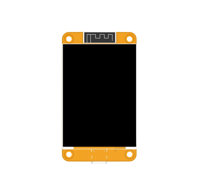
E32R24P-TopView
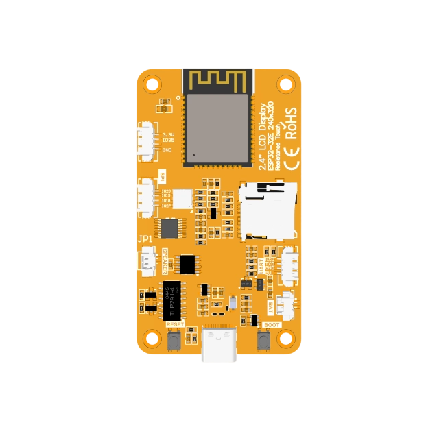
E32R24P-BottomView


Product Description
- Comes with ESP32-32E module, easy development, sufficient development resources
- 2.4-inch color screen, 240x320 resolution ,the maximum support is 262K color (RGB666), display rich color
- Rich interface, easy to connect a variety of peripherals (SPI, UART,etc.)
- Supports external speakers to play audio
- Comes with RGB three-color indicator, indicating rich status
- Comes with resistive touch screen, easy man-machine interaction
- Standard TYPE-C interface for easy program download and power supply
- Equipped with micro TF card slot for easy storage expansion
- Support external lithium battery, lightweight and portable
- Equipped with battery charging management circuit to ensure safe battery charging and discharging
- Provide rich example learning programs, easy to learn
- Provide low-level driver technical support, and update WIKI information online
- Multiple tests for module aging can meet military level standards, supporting long-term stable work
Product Parameters
ESP32 Parameters
| Name | Parameter |
|---|---|
| Module | ESP32-32E |
| CPU | ESP32-D0WD-V3,Xtensa dual-core 32-bit LX6 microprocessor |
| Frequency | 240MHz(Max) |
| Memory | 448KB ROM+520KB SRAM+16KB RTC SRAM+4MB external QSPI Flash |
| WIFI | 2.4GHz and 802.11b/g/n modes |
| Bluetooth | Bluetooth V4.2BR /EDR and Bluetooth LE standards |
| Operating Voltage | 3.0~3.6(V) |
LCD Parameters
| Name | Parameter |
|---|---|
| Panel Size | 2.4 inch |
| Panel Type | IPS TFT |
| Resolution | 240xRGBx320(pixels) |
| Active Area | 36.20(W)x49.0(H) |
| Number of Colors | Max: 262K(RGB666)
Common: 65K(RGB565) |
| Driver IC | ST7789 |
| Display Interface | 4-Line SPI(Connect to ESP32) |
| Pixel Size | 0.15(H)x0.15(mm) |
| View Angle | ALL’CLOCK |
| Brightness(TYP) | 220 cd/m2 |
| Backlight Type | White LED*4 |
| Operation Temperature | -20~60(℃) |
| Storage Temperature | -30~70(℃) |
Touch Screen Parameters
| Name | Parameter |
|---|---|
| Touch Active Area | 2.4 inch |
| Touch Screen Type | Resistive touch screen |
| Driver IC | XPT2046 |
| Touch Screen Visual Area | 38.36(W)x50.70(H)(mm) |
| Communication Interface | SPI |
| Material | ITO film +ITO glass |
| Operation Temperature | -20~60(℃) |
| Storage Temperature | -30~70(℃) |
Size Parameters
| Name | Parameter |
|---|---|
| LCD Outline Size | 42.6±0.2(W)x60±0.2(H)x2.34±0.1(D)(mm)
(Excluding cables and adhesive backing) |
| Touch Screen Outline Size | 42.60±0.2(W)x57.25±0.2(H)x1.0 (D)(mm)
(Excluding cables and adhesive backing) |
| Module Outline Size | 42.89(W)x74.33(H)x5.44(D)(mm) |
Battery Charging Parameters
| Name | Parameter |
|---|---|
| Charging Voltage | Range: 4.2 to 6.5
Typical value: 5 |
| Charging Current | Max: 500
Module Actual value: 367 |
| Charging Saturation Voltage | 4.2V |
| Charging Temperature | Module maximum value:62℃ |
| Rechargeable Battery Specifications | 3.7V polymer lithium battery |
Basic Parameters
| Name | Parameter |
|---|---|
| SKU | E32R24P |
| Power Supply Interface | TYPE-C |
| Weight(including package) | 90g |
Interface Definition

Interface Function Description
| Interface Name | Function Description |
|---|---|
| ESP32-32E Module | Display module main control,control board peripheral and external peripheral. |
| SD card slot | A MicroSD card is inserted to expand the storage space for storing
large data such as characters, pictures, and audio files. |
| RGB three-color light | Contains red, green, blue three colors of LED lights, each light can be controlled by IO,
used to indicate the status. |
| serial port | 1.25mm 4P connector.It can be used for serial debugging, downloading,
and communication. An external USB to serial port module is required. |
| Battery Interface | 1.25mm 2P connector.Used to connect 3.7V polymer lithium battery,
charge the battery through the battery charge management circuit, can also be used for battery power supply. Note the positive and negative terminals of the interface. |
| BOOT KEY | Used to enter download mode or key test.
Press and hold this button to power on and release it to enter the download mode. Alternatively, press and hold this button and then press the RESET button to release the RESET button and then release this button to enter the download mode. When you do not need to enter the download mode, this button can be used as a common button. |
| Type-C Interface | Used for module power supply and download programs.
This interface is connected to the one-click download circuit on the module, which can automatically enter the download mode (without pressing the BOOT key). |
| RESET KEY | Used for ESP32 master control and LCD reset, level reset after pressing. |
| Expansion Pins | 1.25mm 2P connector. Lead out GND, 3.3V, and IO35 pins,
of which IO35 can only be used as the input pin. |
| Speaker Interface | 1.25mm 2P connector. Used to access the speaker to play audio. |
| SPI peripheral interface | 1.25mm 4P connector. For external connection to devices that use IIC communication.
It can be used as ordinary IO. |
ESP32 Pin Assignment
| Onboard Equipment | ESP32 Connect Pins | Pin Description of Onboard Equipment |
|---|---|---|
| LCD | IO15 | LCD screen selection control signal, low level effective |
| IO2 | LCD command/data selection control signal
High Level:data,low Level:command | |
| IO14 | LCD SPI bus clock signal | |
| IO13 | LCD SPI bus write data signal | |
| EN | LCD reset control signal, low level reset(share reset pin with ESP32-32E master) | |
| IO21 | LCD backlight control signal(high level backlight on, low level backlight off) | |
| Resistive Touch Screen | IO25 | Resistive touch screen SPI bus clock signal |
| IO32 | Resistive touch screen SPI bus write data signal | |
| IO39 | Resistive touch screen SPI bus read data signal | |
| IO33 | Resistive touch screen chip selection control signal,low level effective | |
| IO36 | Resistive touch screen touch interrupt signal,
generates touch when input low level to master | |
| RGB Three-color Light | IO22 | Red LED light(common anode, low level on, high level off) |
| IO16 | Green LED light(common anode, low level on, high level off) | |
| IO17 | Blue LED light(common anode, low level on, high level off) | |
| MicroSD 卡 | IO5 | SD card select signal,low level effective |
| IO23 | SD card SPI bus write data signal
(shared by MicroSD card and SPI peripheral) | |
| IO18 | SD card SPI bus clock signal
(shared by MicroSD card and SPI peripheral) | |
| IO19 | SD card SPI bus read data signal
(shared by MicroSD card and SPI peripheral) | |
| Audio | IO4 | Audio enable signal,low level enable,high level disable |
| IO26 | Audio signal DAC output signal | |
| KEY | IO0 | Download mode Select button
(Press and hold the button to power on, then release to enter download mode) |
| EN | ESP32-23E reset button, low level reset(shared with LCD reset) | |
| Serial Port | RXD0(IO3) | ESP32-32E serial port receiving signal
(if the serial port is not used, it can be used as ordinary IO) |
| TXD0(IO1) | ESP32-32E serial port sends signals
(if the serial port is not used, it can be used as ordinary IO) | |
| Battery | IO34 | Battery voltage ADC value Get Signal (input) |
| SPI Peripheral | IO27 | SPI peripheral chip selection signal, low level effective
(if the SPI device is not used, it can be used for ordinary IO) |
| IO18 | SPI bus clock pin for SPI peripherals
(SPI peripherals are shared with MicroSD cards, if SPI devices or SD cards are not used, ordinary IO can be used) | |
| IO19 | The SPI bus read data pin of the SPI peripheral
(SPI peripherals are shared with MicroSD cards, if SPI devices or SD cards are not used, ordinary IO can be used) | |
| IO23 | The SPI bus of the SPI peripheral writes data pins
(SPI peripherals are shared with MicroSD cards, if SPI devices or SD cards are not used, ordinary IO can be used) | |
| NC | IO35 | It can only be used as input IO |
Quick Start Instructions
![]() 2.4-inch ESP32-32E display module Quick_Start Package
2.4-inch ESP32-32E display module Quick_Start Package
![]() 2.4-inch ESP32-32E display module Qucik Start
2.4-inch ESP32-32E display module Qucik Start
Data Pack Download
Download the data package
![]() 2.4inch ESP32-32E-ST7789 LCD Module Data package(Extract code:h8hh)
2.4inch ESP32-32E-ST7789 LCD Module Data package(Extract code:h8hh)
Product Documentation
Specification
Product Specification
![]() 2.4-inch ESP32-32E display module Specification
2.4-inch ESP32-32E display module Specification
LCD Specifications
User Manual
![]() 2.4-inch ESP32-32E display module User Manual
2.4-inch ESP32-32E display module User Manual
Dimension Drawing
![]() E32R24P display module dimensions
E32R24P display module dimensions
3D Drawing
![]() E32R24P display module 3D image
E32R24P display module 3D image
Schematic
![]() 2.4-inch ESP32-32E display module Schematic diagram
2.4-inch ESP32-32E display module Schematic diagram
IO Resource Allocation Table
![]() ESP32 IO resource allocation table
ESP32 IO resource allocation table
Package Library
![]() 2.4-inch ESP32-32E display module AD package library
2.4-inch ESP32-32E display module AD package library
LCD Initialization Code
Reference Materials
Development environment construction
![]() Arduino IDE1 development environment construction for ESP32
Arduino IDE1 development environment construction for ESP32
![]() Arduino IDE2 development environment construction for ESP32
Arduino IDE2 development environment construction for ESP32
![]() MicroPython development environment construction for ESP32
MicroPython development environment construction for ESP32
![]() ESP-IDF using VSCODE development environment construction for ESP32
ESP-IDF using VSCODE development environment construction for ESP32
![]() ESP-IDF LVGL porting construction for ESP32
ESP-IDF LVGL porting construction for ESP32
Demo Instructions
![]() 2.4-inch ESP32-32E display module Arduino Demo Instructions
2.4-inch ESP32-32E display module Arduino Demo Instructions
![]() 2.4-inch ESP32-32E display module MicroPython Demo Instructions
2.4-inch ESP32-32E display module MicroPython Demo Instructions
![]() 2.4-inch ESP32-32E display module ESP-IDF Demo Instructions
2.4-inch ESP32-32E display module ESP-IDF Demo Instructions
Datasheet
![]() ESP32 hardware design guidelines
ESP32 hardware design guidelines
![]() ESP32 technical reference manual
ESP32 technical reference manual
![]() Battery Charging Management TP4054 Datasheet
Battery Charging Management TP4054 Datasheet
![]() Audio amplifier FM8002E Datasheet
Audio amplifier FM8002E Datasheet
![]() USB to serial port CH340C Datasheet
USB to serial port CH340C Datasheet
![]() Chinese and English display modulo settings
Chinese and English display modulo settings
Tool Software
![]() Flash_Download_Tool(Official website download)
Flash_Download_Tool(Official website download) ![]() Flash_Download_Tool
Flash_Download_Tool