More languages
More actions
No edit summary |
No edit summary |
||
| (11 intermediate revisions by 3 users not shown) | |||
| Line 1: | Line 1: | ||
[[ | [[zh:4.0inch_ESP32-32E_Display]] | ||
{{#widget:StyledHeader | {{#widget:StyledHeader | ||
| color = #bc1d46 | | color = #bc1d46 | ||
| Line 10: | Line 10: | ||
{{gallery|width=350px|height=350px | {{gallery|width=350px|height=350px | ||
|File:E32N40T-01.png| | |File:E32N40T-01.png|E32N40T-TopView | ||
|File:E32N40T-02.png|E32N40T--BottomView | |File:E32N40T-02.png|E32N40T--BottomView | ||
}} | }} | ||
| Line 101: | Line 101: | ||
|- | |- | ||
| align="center" |'''Operating Temperature''' | | align="center" |'''Operating Temperature''' | ||
| align="center" |- | | align="center" | -20~60(℃) | ||
|- | |- | ||
| align="center" |'''Storage Temperature''' | | align="center" |'''Storage Temperature''' | ||
| align="center" |- | | align="center" | -30~70(℃) | ||
|} | |} | ||
| Line 190: | Line 190: | ||
| align="center" |When ESP32 is reset: 40mA | | align="center" |When ESP32 is reset: 40mA | ||
When only the display screen is working: 230mA | When only the display screen is working: 230mA | ||
When the display screen, speaker, and battery charging are all working: 580mA | When the display screen, speaker, and battery charging are all working: 580mA | ||
|- | |- | ||
| Line 196: | Line 197: | ||
|- | |- | ||
|'''Backlight Brightness (Actual Value)''' | |'''Backlight Brightness (Actual Value)''' | ||
|With touch screen: 370 cd/m<sup>2</sup> Without touch screen: 472 cd/m<sup>2</sup> | |With touch screen: 370 cd/m<sup>2</sup> | ||
Without touch screen: 472 cd/m<sup>2</sup> | |||
|- | |- | ||
|'''Supported Speaker Power Consumption (Maximum)''' | |'''Supported Speaker Power Consumption (Maximum)''' | ||
| Line 220: | Line 222: | ||
= Interface Definition = | = Interface Definition = | ||
[[File:E32R40T- | [[File:E32R40T-06.png|956x956 pixels]] | ||
== Interface Function Description == | == Interface Function Description == | ||
| Line 269: | Line 271: | ||
|1.25mm 4P socket. Used to connect external IIC communication devices. It can be used as a normal IO. | |1.25mm 4P socket. Used to connect external IIC communication devices. It can be used as a normal IO. | ||
|} | |} | ||
== ESP32 Pin Assignment == | |||
{| class="wikitable prettytable" | |||
! align="center" |'''On-board Device''' | |||
! align="center" |'''ESP32 Connected Pin''' | |||
! align="center" |'''On-board Device Pin Description''' | |||
|- | |||
| rowspan="7" align="center" |'''Liquid Crystal Display (LCD)''' | |||
| align="center" |IO15 | |||
|LCD chip select control signal, valid at low level | |||
|- | |||
| align="center" |IO2 | |||
|LCD command/data selection control signal | |||
High level: data, Low level: command | |||
|- | |||
| align="center" |IO14 | |||
|SPI bus clock signal (shared by the LCD and the resistive touch screen) | |||
|- | |||
| align="center" |IO13 | |||
|SPI bus write data signal (shared by the LCD and the resistive touch screen) | |||
|- | |||
| align="center" |IO12 | |||
|SPI bus read data signal (shared by the LCD and the resistive touch screen) | |||
|- | |||
| align="center" |EN | |||
|LCD reset control signal, resets at low level (shares the reset pin with the ESP32-32E main control) | |||
|- | |||
| align="center" |IO27 | |||
|LCD backlight control signal (turns on the backlight at high level, turns off the backlight at low level) | |||
|- | |||
| rowspan="5" align="center" |'''Resistive Touch Screen''' | |||
| align="center" |IO14 | |||
|SPI bus clock signal (shared by the touch screen and the LCD) | |||
|- | |||
| align="center" |IO13 | |||
|SPI bus write data signal (shared by the touch screen and the LCD) | |||
|- | |||
| align="center" |IO12 | |||
|SPI bus read data signal (shared by the touch screen and the LCD) | |||
|- | |||
| align="center" |IO33 | |||
|Resistive touch screen chip select control signal, valid at low level | |||
|- | |||
| align="center" |IO36 | |||
|Resistive touch screen touch interrupt signal, inputs a low level to the main control when a touch occurs | |||
|- | |||
| rowspan="3" align="center" |'''RGB Tricolor LED''' | |||
| align="center" |IO22 | |||
|Red LED (common anode, turns on at low level, turns off at high level) | |||
|- | |||
| align="center" |IO16 | |||
|Green LED (common anode, turns on at low level, turns off at high level) | |||
|- | |||
| align="center" |IO17 | |||
|Blue LED (common anode, turns on at low level, turns off at high level) | |||
|- | |||
| rowspan="4" align="center" |'''MicroSD Card''' | |||
| align="center" |IO5 | |||
|SD card chip select signal, valid at low level | |||
|- | |||
| align="center" |IO23 | |||
|SD card SPI bus write data signal (shared by the MicroSD card and SPI peripherals) | |||
|- | |||
| align="center" |IO18 | |||
|SD card SPI bus clock signal (shared by the MicroSD card and SPI peripherals) | |||
|- | |||
| align="center" |IO19 | |||
|SD card SPI bus read data signal (shared by the MicroSD card and SPI peripherals) | |||
|- | |||
| rowspan="2" align="center" |'''Audio''' | |||
| align="center" |IO4 | |||
|Audio enable signal, enables at low level, disables at high level | |||
|- | |||
| align="center" |IO26 | |||
|Audio signal DAC output signal | |||
|- | |||
| rowspan="2" align="center" |'''Button''' | |||
| align="center" |IO0 | |||
|Download mode selection button (enter the download mode by powering on while holding this button and then releasing it) | |||
|- | |||
| align="center" |EN | |||
|ESP32-23E reset button, resets at low level (shares the reset function with the LCD reset) | |||
|- | |||
| rowspan="2" align="center" |'''Serial Port''' | |||
| align="center" |RXD0(IO3) | |||
|ESP32-32E serial port receive signal (can be used as a normal IO if the serial port is not used) | |||
|- | |||
| align="center" |TXD0(IO1) | |||
|ESP32-32E serial port transmit signal (can be used as a normal IO if the serial port is not used) | |||
|- | |||
| align="center" |'''Battery''' | |||
| align="center" |IO34 | |||
|Battery voltage ADC value acquisition signal (input) | |||
|- | |||
| rowspan="4" align="center" |'''SPI Peripherals''' | |||
| align="center" |IO21 | |||
|SPI peripheral chip select signal, valid at low level (can be used as a normal IO if no SPI device is used) | |||
|- | |||
| align="center" |IO18 | |||
|SPI bus clock pin of the SPI peripheral | |||
(Shared by the SPI peripheral and the MicroSD card. Can be used as a normal IO if neither the SPI device nor the SD card is used) | |||
|- | |||
| align="center" |IO19 | |||
|SPI bus read data pin of the SPI peripheral | |||
(Shared by the SPI peripheral and the MicroSD card. Can be used as a normal IO if neither the SPI device nor the SD card is used) | |||
|- | |||
| align="center" |IO23 | |||
|SPI bus write data pin of the SPI peripheral | |||
(Shared by the SPI peripheral and the MicroSD card. Can be used as a normal IO if neither the SPI device nor the SD card is used) | |||
|- | |||
| rowspan="2" align="center" |'''I2C Peripherals''' | |||
| align="center" |IO25 | |||
|I2C bus clock pin of the I2C peripheral (can be used as a normal IO if no I2C device is used) | |||
|- | |||
| align="center" |IO32 | |||
|I2C bus data pin of the I2C peripheral (can be used as a normal IO if no I2C device is used) | |||
|- | |||
| rowspan="2" align="center" |'''Unused''' | |||
| align="center" |IO35 | |||
| rowspan="2" |Can only be used as an input IO | |||
|- | |||
| align="center" |IO39 | |||
|- | |||
|} | |||
= Quick Use Instructions = | |||
[[File:Zip-001.png|24x24px]] [[:en:res/E32R40T/4.0inch_ESP32-32E_E32R40T_E32N40T_Quick_Start.zip|'''Quick Use Data Package of 4.0-inch ESP32-32E Display Module''']] | |||
[[File:HTML-001.jpg|24x24px]] [[:en:ESP32-32E display module Qucik Start|'''Quick Use Instructions of 4.0-inch ESP32-32E Display Module''']] | |||
= Data Package Download = | |||
= Data Pack Download = | |||
High-Speed Cloud Disk Sharing-Link1:[[File:Zip-001.png|24x24px]] [https://www.123865.com/s/Kg5Wvd-nEGr3'''4.0inch_ESP32-32E_ST7796_E32R40T_E32N40T_V1.0'''] | |||
Baidu Cloud Disk Download-Link3:[[File:Zip-001.png|24x24px]] [https://pan.baidu.com/s/1mc_u8u2IyE0bfbBE3tA50w?pwd=92ef '''4.0inch_ESP32-32E_ST7796_E32R40T_E32N40T_V1.0(Extraction Code: 92ef)'''] | |||
High-Speed Cloud Disk Download-Link4:[[File:Zip-001.png|24x24px]] [https://1855123618.v.123pan.cn/1855123618/24207537 '''4.0inch_ESP32-32E_ST7796_E32R40T_E32N40T_V1.0'''] | |||
= Product Documents = | |||
== Specification Documents == | |||
==== Module Specification Document ==== | |||
[[File:Pdf-001.jpg|24x24px]] [[:en:res/E32R40T/E32R40T_E32N40T_Specification_V1.0.pdf|'''Product Specification Document of 4.0-inch ESP32-32E Display Module''']] | |||
==== Liquid Crystal Screen Specification Document ==== | |||
[[File:Pdf-001.jpg|24x24px]] [[:en:res/E32R40T/QD3958-Specifications-A.pdf|'''Specification Document of 4.0-inch QD3958 Screen''']] | |||
== User Manual == | |||
[[File:Pdf-001.jpg|24x24px]] [[:en:res/E32R40T/4.0inch_ESP32-32E_E32R40T_E32N40T_User_Manual.pdf|'''User Manual of 4.0-inch ESP32-32E Display Module''']] | |||
== Module Dimension Diagram == | |||
[[File:Pdf-001.jpg|24x24px]] [[:en:res/E32R40T/E32R40T_Size.pdf|'''Dimension Diagram of E32R40T Display Module''']] | |||
[[File:Pdf-001.jpg|24x24px]] [[:en:res/E32R40T/E32N40T_Size.pdf|'''Dimension Diagram of E32N40T Display Module''']] | |||
== 3D Structure Diagram (.step File) == | |||
[[File:Zip-001.png|24x24px]] [[:en:res/E32R40T/E32R40T_3D.zip|'''3D Diagram of E32R40T Display Module''']] | |||
[[File:Zip-001.png|24x24px]] [[:en:res/E32R40T/E32N40T_3D.zip|'''3D Diagram of E32N40T Display Module''']] | |||
== Module Schematic Diagram == | |||
[[File:Pdf-001.jpg|24x24px]] [[:en:res/E32R40T/4.0inch_ESP32-32E_E32R40T_E32N40T_Schematic.pdf|'''Schematic Diagram of 4.0-inch ESP32-32E Display Module''']] | |||
== IO Resource Allocation Table == | |||
[[File:Excel-001.png|24x24px]] [[:en:res/E32R40T/ESP32-32E模组IO资源分配表.xlsx|'''ESP32 IO Resource Allocation Table''']] | |||
== Package Library == | |||
[[File:Zip-001.png|24x24px]] [[:en:res/E32R40T/4.0inch_ESP32-32E_E32R40T_E32N40T_AD封装库.zip|'''AD Package Library of 4.0-inch ESP32-32E Display Module''']] | |||
== LCD Initialization Code == | |||
[[File:Txt-002.jpg|24x24px]] [[:en:res/E32R40T/ST7796_Init.txt|'''ST7796 Initialization Code''']] | |||
= Reference Materials = | |||
== Development Environment Setup == | |||
[[File:Pdf-001.jpg|24x24px]] [[:en:res/PublicFile/Arduino_IDE1_development_environment_construction_for_ESP32.pdf|'''Arduino IDE1 development environment construction for ESP32''']] | |||
[[File:Pdf-001.jpg|24x24px]] [[:en:res/PublicFile/Arduino_IDE2_development_environment_construction_for_ESP32.pdf|'''Arduino IDE2 development environment construction for ESP32''']] | |||
[[File:Pdf-001.jpg|24x24px]] [[:en:res/PublicFile/MicroPython_development_environment_construction_for_ESP32.pdf|'''MicroPython development environment construction for ESP32''']] | |||
[[File:Pdf-001.jpg|24x24px]] [[:en:res/PublicFile/Building_an_ESP-IDF_environment_using_VSCode.pdf|'''ESP-IDF using VSCODE development environment construction for ESP32''']] | |||
[[File:Pdf-001.jpg|24x24px]] [[:en:res/PublicFile/ESP-IDF_LVGL_porting_instructions.pdf|'''ESP-IDF LVGL porting construction for ESP32''']] | |||
== Instructions for Using Supporting Example Codes == | |||
[[File:Pdf-001.jpg|24x24px]] [[:en:res/E32R40T/4.0inch_E32R40T_E32N40T_Arduino_Demo_Instructions.pdf|'''Instructions for Arduino Example Programs of 4.0-inch ESP32-32E Display Module''']] | |||
[[File:Pdf-001.jpg|24x24px]] [[:en:res/E32R40T/4.0inch_E32R40T_E32N40T_MicroPython_Demo_Instructions.pdf|'''Instructions for MicroPython Example Programs of 4.0-inch ESP32-32E Display Module''']] | |||
[[File:Pdf-001.jpg|24x24px]] [[:en:res/E32R40T/4.0inch_E32R40T_E32N40T_ESP-IDF_Demo_Instructions.pdf|'''Instructions for ESP-IDF Example Programs of 4.0-inch ESP32-32E Display Module''']] | |||
== Other Reference Data Manuals == | |||
[[File:Pdf-001.jpg|24x24px]] [[:en:res/E32R40T/ST7796S-Sitronix.pdf|'''ST7796S Data Manual''']] | |||
[[File:Pdf-001.jpg|24x24px]] [[:en:res/PublicFile/XPT2046.pdf|'''XPT2046 Datasheet''']] | |||
[[File:Pdf-001.jpg|24x24px]] [[:en:res/PublicFile/esp32_datasheet_en.pdf|'''ESP32 Datasheet''']] | |||
[[File:Pdf-001.jpg|24x24px]] [[:en:res/PublicFile/esp32-wroom-32e_esp32-wroom-32ue_datasheet_en.pdf|'''ESP32-32E Module Datasheet''']] | |||
[[File:Pdf-001.jpg|24x24px]] [[:en:res/PublicFile/esp32_hardware_design_guidelines_en.pdf|'''ESP32 hardware design guidelines''']] | |||
[[File:Pdf-001.jpg|24x24px]] [[:en:res/PublicFile/esp32_technical_reference_manual_en.pdf|'''ESP32 technical reference manual''']] | |||
[[File:Pdf-001.jpg|24x24px]] [[:en:res/PublicFile/TP4054.PDF|'''Battery Charging Management TP4054 Datasheet''']] | |||
[[File:Pdf-001.jpg|24x24px]] [[:en:res/PublicFile/ME6217_LDO.pdf|'''Regulator ME6217 Datasheet''']] | |||
[[File:Pdf-001.jpg|24x24px]] [[:en:res/PublicFile/FM8002E.pdf|'''Audio amplifier FM8002E Datasheet''']] | |||
[[File:Pdf-001.jpg|24x24px]] [[:en:res/PublicFile/CH340C_en.pdf|'''USB to serial port CH340C Datasheet''']] | |||
[[File:HTML-001.jpg|24x24px]] [[:en:Chinese_and_English_display_modulo_settings|'''Chinese and English display modulo settings''']] | |||
= Tool Software = | |||
[[File:Zip-001.png|24x24px]] [https://dl.espressif.com/public/flash_download_tool.zip '''Flash_Download_Tool(Official website download)'''] | |||
[[File:Zip-001.png|24x24px]] [[:en:res/software/Flash_Download.zip|'''Flash_Download_Tool''']] | |||
[[File:Zip-001.png|24x24px]] [[:en:res/software/JPGCompact_V5.0.zip|'''JPGCompact''']] | |||
[[File:Zip-001.png|24x24px]] [[:en:res/software/TCP_UDP测试工具.zip|'''TCP_UDP test tool''']] | |||
[[File:Zip-001.png|24x24px]] [[:en:res/software/USB-SERIAL_CH340.zip|'''USB-SERIAL_CH340''']] | |||
[[File:Zip-001.png|24x24px]] [[:en:res/software/串口调试助手.zip|'''Serial debugging assistant''']] | |||
[[File:Zip-001.png|24x24px]] [[:en:res/software/网络调试助手.zip|'''Network debugging assistant''']] | |||
[[File:APK-001.png|24x24px]] [[:en:res/software/esptouch-v2.0.0.apk|'''esptouch''']] | |||
[[File:Zip-001.png|24x24px]] [[:en:res/software/PCtoLCD2002.zip|'''PCtoLCD2002''']] | |||
[[File:Zip-001.png|24x24px]] [[:en:res/software/Image2Lcd.zip|'''Image2Lcd''']] | |||
Latest revision as of 15:28, 26 January 2026
Product Images
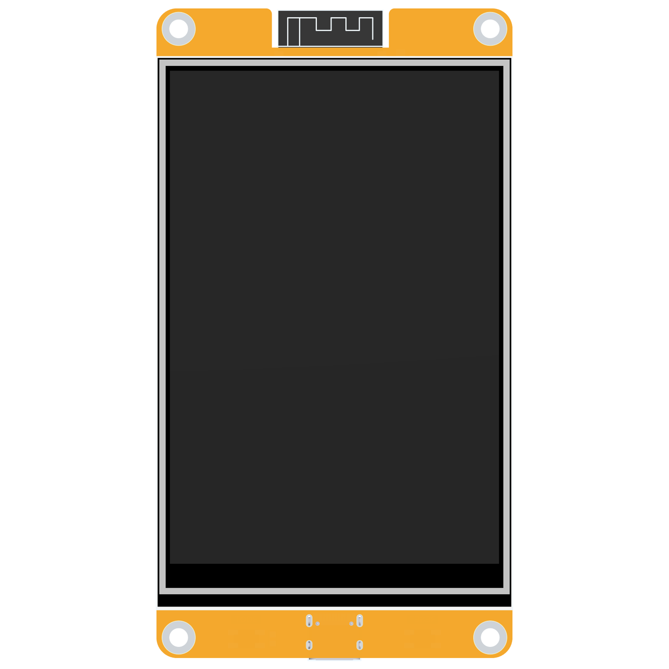
E32R40T-TopView
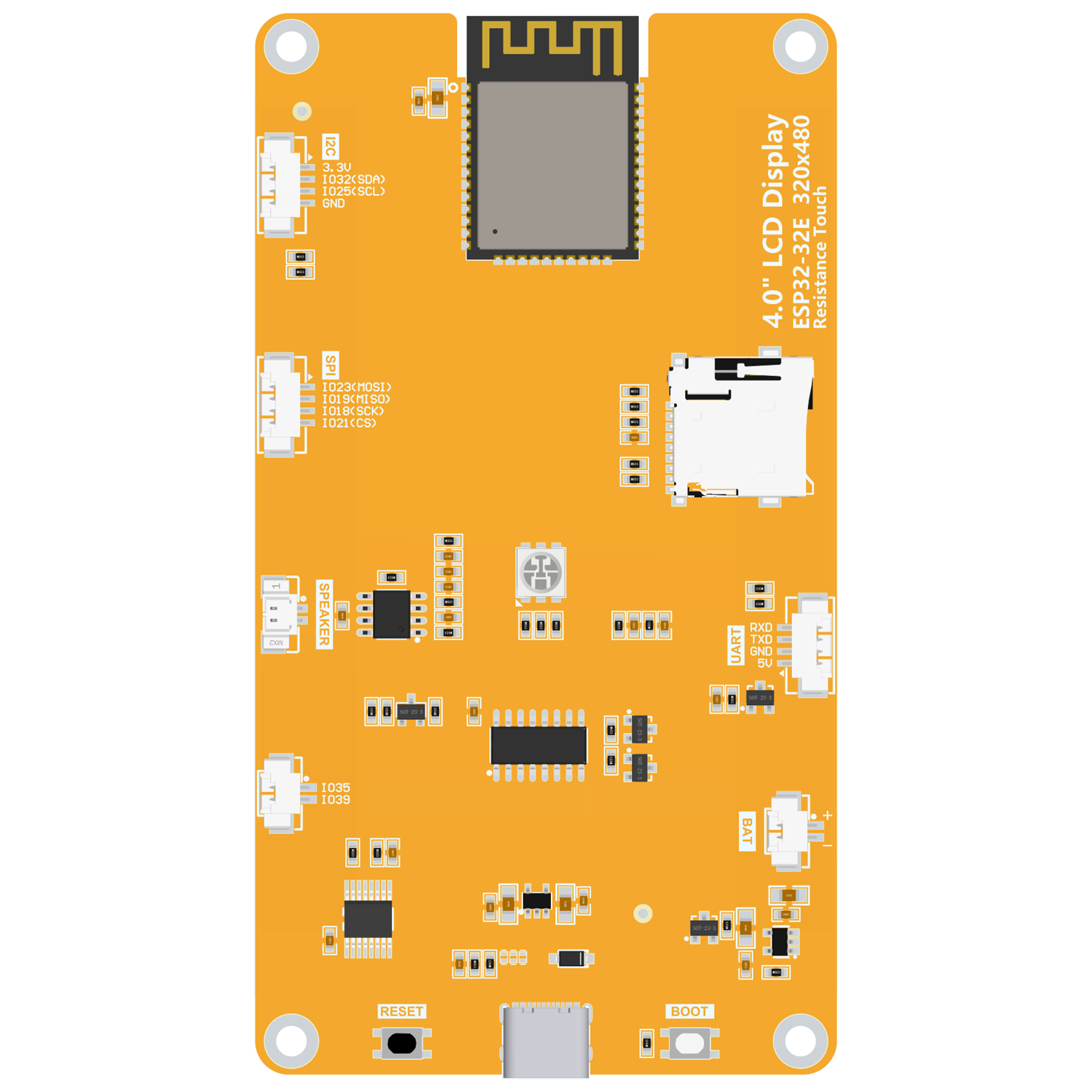
E32R40T-BottomView


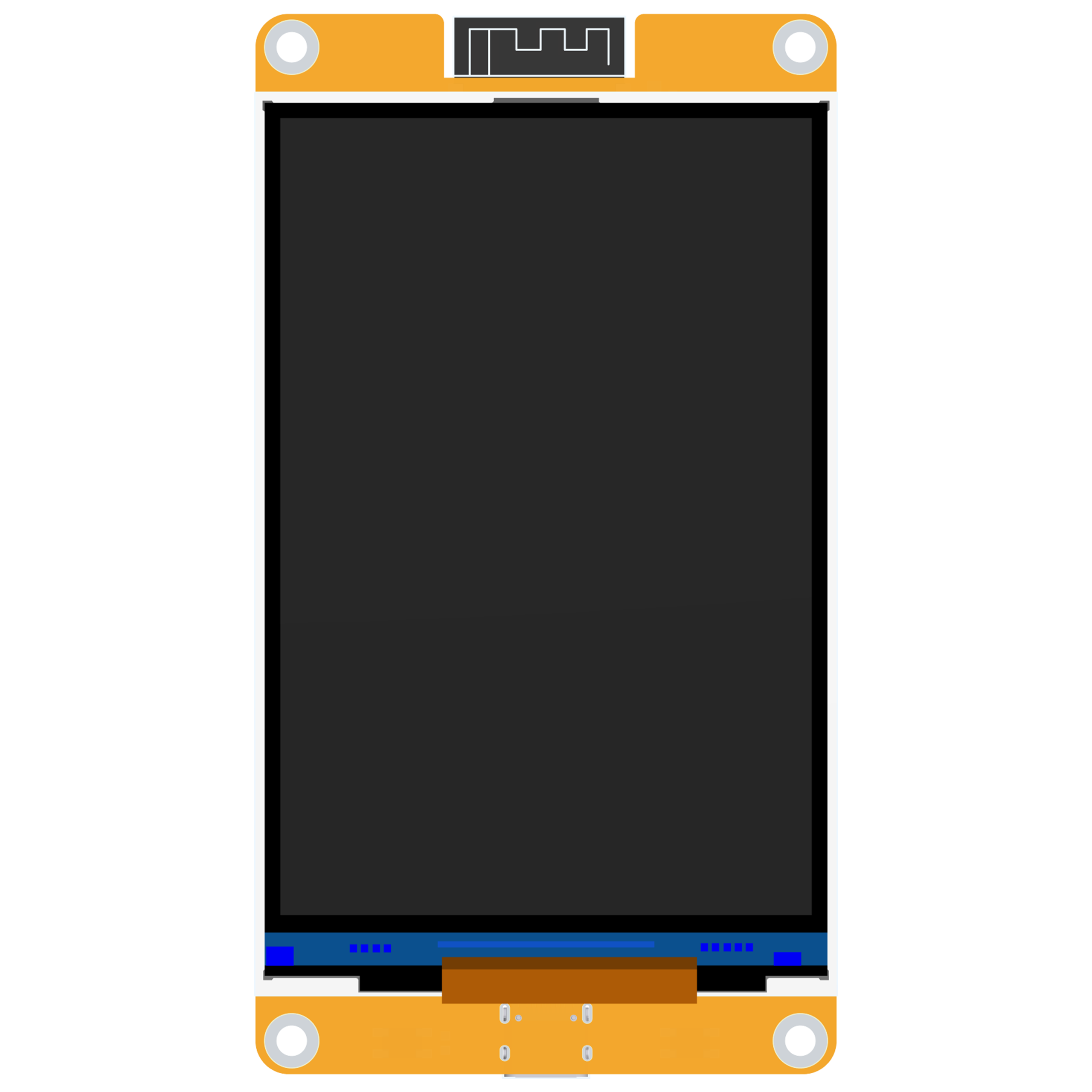
E32N40T-TopView
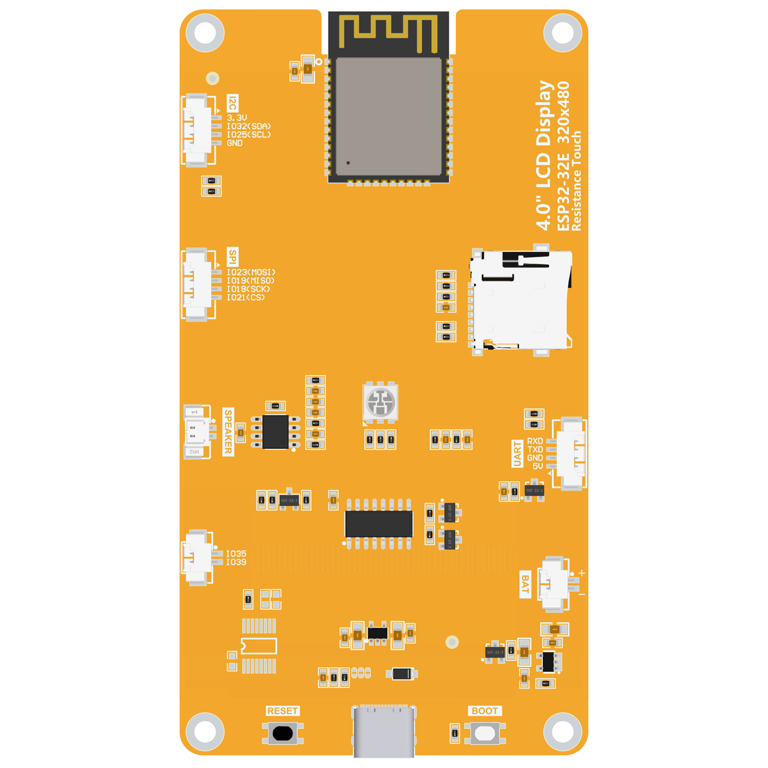
E32N40T--BottomView


Product Introduction
- Comes with an ESP32-32E module, facilitating development and providing ample development resources.
- 3.95/4.0-inch color screen with a resolution of 320x480, supporting up to 262K colors (RGB666), offering rich color display.
- Abundant interfaces, making it convenient to connect various peripherals (such as I2C, SPI, UART and other peripherals).
- Supports external speakers for audio playback.
- Equipped with an RGB tricolor indicator light, providing diverse status indications.
- Comes with a resistive touch screen, enabling convenient human-computer interaction.
- Standard TYPE-C interface, enabling easy program downloading and power supply.
- Has a micro TF card slot for easy storage expansion.
- Supports external lithium batteries, being lightweight and portable.
- Features a battery charging management circuit to ensure the safe charging and discharging of the battery.
- Provides a wealth of example programs, making it easy to learn.
- Offers underlying driver technical support, and WIKI materials are updated online.
- The module has passed multiple aging tests and can meet military-grade standards, ensuring long-term stable operation.
Product Parameters
ESP32 Main Control Parameters
| Name | Parameters |
|---|---|
| Module | ESP32-32E |
| CPU | ESP32-D0WD-V3, Xtensa dual-core 32-bit LX6 microprocessor |
| Main Frequency | 240MHz (maximum) |
| Storage | 448KB ROM + 520KB SRAM + 16KB RTC SRAM + 4MB external QSPI Flash |
| WIFI | 2.4GHz, 802.11b/g/n mode |
| Bluetooth | Bluetooth V4.2 BR/EDR and Bluetooth LE standards |
| Operating Voltage | 3.0~3.6(V) |
| Operating Temperature | –40~85(℃) |
Liquid Crystal Screen Parameters
| Name | Parameters |
|---|---|
| Screen Size | 3.95/4.0 inch |
| Screen Type | TN TFT |
| Resolution | 320xRGBx480(pixels) |
| Effective Display Area | 55.68(W)x83.52(H)(mm) |
| Number of Colors | Maximum: 262K(RGB666)
Commonly used: 65K(RGB565) |
| Driver IC | ST7796S |
| Display Interface | 4-Line SPI(connected to ESP32) |
| Pixel Size | 0.174(H)x0.174(mm) |
| Viewing Angle | 12 0’CLOCK |
| Backlight Brightness (Typical Value) | 450cd/m2 |
| Backlight Type | White LED*8 |
| Operating Temperature | -20~60(℃) |
| Storage Temperature | -30~70(℃) |
Touch Screen Parameters
| Name | Parameters |
|---|---|
| Effective Area Size | 3.95 inch |
| Touch Screen Type | Resistive touch screen |
| Driver IC | XPT2046 |
| Effective Touch Area | 56.28(W)x84.32(H)(mm) |
| Visible Window Size | 56.88(W)x85.22(H)(mm) |
| Communication Interface | SPI |
| Structural Material | ITO film + ITO glass |
| Operating Temperature | -10~60(℃) |
| Storage Temperature | -20~70(℃) |
Size Parameters
| Name | Parameters |
|---|---|
| Liquid Crystal Screen Outline Dimensions | 60.88±0.2(W)x94.57±0.2(H)x2.5±0.1(D)(mm)(excluding the cable and back adhesive) |
| Touch Screen Outline Dimensions | 60.48±0.2(W)x93.87±0.2(H)x1.05±0.1(D)(mm)(excluding the cable and back adhesive) |
| Module Outline Dimensions | With touch screen: 60.88(W)x111.11(H)x5.65(D)(mm)
Without touch screen: 60.88(W)x111.11(H)x4.60(D)(mm) |
Battery Charging Parameters
| Name | Parameters |
|---|---|
| Charging Voltage | Range: 4.2~6.5(V)
Typical value: 5V |
| Charging Current | Maximum value: 500mA
Module actual value: 290mA |
| Charging Saturation Voltage | 4.24V |
| Charging Temperature | Module actual maximum value: 62℃ |
| Charging Battery Specifications | 3.7V polymer lithium battery |
Electrical Parameters
| Name | Parameters |
|---|---|
| Operating Voltage | 5.0V |
| Backlight Current | 142mA |
| Total Current | When ESP32 is reset: 40mA
When only the display screen is working: 230mA When the display screen, speaker, and battery charging are all working: 580mA |
| Power Consumption | 1.15W (when only the display screen is working) |
| Backlight Brightness (Actual Value) | With touch screen: 370 cd/m2
Without touch screen: 472 cd/m2 |
| Supported Speaker Power Consumption (Maximum) | 1.5W(8Ω) or 2W(4Ω) |
Basic Parameters
| Name | Parameters |
|---|---|
| SKU |
With touch screen: E32R40T |
| Power Supply Interface | TYPE-C |
| Weight (Including Packaging) | E32R40T: 130 g
E32N40T: 119 g |
Interface Definition

Interface Function Description
| Interface | Function Description |
|---|---|
| ESP32-32E Module | The main control of the display module, which controls on-board peripherals and external peripherals. |
| MicroSD Card Slot | Insert a Micro SD card to expand the storage space, for example, to store large data such as font libraries, pictures, and audio files. |
| RGB Tricolor Light | Includes red, green, and blue LED lights, and each light can be controlled by an IO pin to indicate the status. |
| Serial Port | 1.25mm 4P socket. It can be used for serial port debugging, downloading, and communication. An external USB-to-serial port module is required. |
| Battery Interface | 1.25mm 2P socket, used to connect a 3.7V polymer lithium battery.
The battery is charged through the battery charging management circuit and can also be used for battery power supply. Pay attention to the positive and negative poles of the interface. |
| BOOT Button | Used to enter the download mode or conduct button testing.
Press and hold this button while powering on, then release it to enter the download mode. Or after powering on, press and hold this button, then press the RESET button, release the RESET button, and then release this button to enter the download mode. When there is no need to enter the download mode, this button can be used as a regular button. |
| TYPE-C Interface | Used for module power supply and program downloading. This interface is connected to the one-click download circuit on the module,
allowing it to automatically enter the download mode (no need to press the BOOT button). |
| RESET Button | Used to reset the ESP32 main control and the LCD. Press it for level reset. |
| Expansion Input Pins | 1.25mm 2P socket. IO35 and IO39 are two IO pins with only input functions, used to connect input signals. |
| Speaker Interface | 1.25mm 2P socket. Used to connect a speaker for audio playback. |
| SPI Peripheral Interface | 1.25mm 4P socket. Used to connect external SPI communication devices. This SPI interface is shared with the MicroSD. It can be used as a normal IO. |
| I2C Peripheral Interface | 1.25mm 4P socket. Used to connect external IIC communication devices. It can be used as a normal IO. |
ESP32 Pin Assignment
| On-board Device | ESP32 Connected Pin | On-board Device Pin Description |
|---|---|---|
| Liquid Crystal Display (LCD) | IO15 | LCD chip select control signal, valid at low level |
| IO2 | LCD command/data selection control signal
High level: data, Low level: command | |
| IO14 | SPI bus clock signal (shared by the LCD and the resistive touch screen) | |
| IO13 | SPI bus write data signal (shared by the LCD and the resistive touch screen) | |
| IO12 | SPI bus read data signal (shared by the LCD and the resistive touch screen) | |
| EN | LCD reset control signal, resets at low level (shares the reset pin with the ESP32-32E main control) | |
| IO27 | LCD backlight control signal (turns on the backlight at high level, turns off the backlight at low level) | |
| Resistive Touch Screen | IO14 | SPI bus clock signal (shared by the touch screen and the LCD) |
| IO13 | SPI bus write data signal (shared by the touch screen and the LCD) | |
| IO12 | SPI bus read data signal (shared by the touch screen and the LCD) | |
| IO33 | Resistive touch screen chip select control signal, valid at low level | |
| IO36 | Resistive touch screen touch interrupt signal, inputs a low level to the main control when a touch occurs | |
| RGB Tricolor LED | IO22 | Red LED (common anode, turns on at low level, turns off at high level) |
| IO16 | Green LED (common anode, turns on at low level, turns off at high level) | |
| IO17 | Blue LED (common anode, turns on at low level, turns off at high level) | |
| MicroSD Card | IO5 | SD card chip select signal, valid at low level |
| IO23 | SD card SPI bus write data signal (shared by the MicroSD card and SPI peripherals) | |
| IO18 | SD card SPI bus clock signal (shared by the MicroSD card and SPI peripherals) | |
| IO19 | SD card SPI bus read data signal (shared by the MicroSD card and SPI peripherals) | |
| Audio | IO4 | Audio enable signal, enables at low level, disables at high level |
| IO26 | Audio signal DAC output signal | |
| Button | IO0 | Download mode selection button (enter the download mode by powering on while holding this button and then releasing it) |
| EN | ESP32-23E reset button, resets at low level (shares the reset function with the LCD reset) | |
| Serial Port | RXD0(IO3) | ESP32-32E serial port receive signal (can be used as a normal IO if the serial port is not used) |
| TXD0(IO1) | ESP32-32E serial port transmit signal (can be used as a normal IO if the serial port is not used) | |
| Battery | IO34 | Battery voltage ADC value acquisition signal (input) |
| SPI Peripherals | IO21 | SPI peripheral chip select signal, valid at low level (can be used as a normal IO if no SPI device is used) |
| IO18 | SPI bus clock pin of the SPI peripheral
(Shared by the SPI peripheral and the MicroSD card. Can be used as a normal IO if neither the SPI device nor the SD card is used) | |
| IO19 | SPI bus read data pin of the SPI peripheral
(Shared by the SPI peripheral and the MicroSD card. Can be used as a normal IO if neither the SPI device nor the SD card is used) | |
| IO23 | SPI bus write data pin of the SPI peripheral
(Shared by the SPI peripheral and the MicroSD card. Can be used as a normal IO if neither the SPI device nor the SD card is used) | |
| I2C Peripherals | IO25 | I2C bus clock pin of the I2C peripheral (can be used as a normal IO if no I2C device is used) |
| IO32 | I2C bus data pin of the I2C peripheral (can be used as a normal IO if no I2C device is used) | |
| Unused | IO35 | Can only be used as an input IO |
| IO39 |
Quick Use Instructions
![]() Quick Use Data Package of 4.0-inch ESP32-32E Display Module
Quick Use Data Package of 4.0-inch ESP32-32E Display Module
![]() Quick Use Instructions of 4.0-inch ESP32-32E Display Module
Quick Use Instructions of 4.0-inch ESP32-32E Display Module
Data Package Download
Data Pack Download
High-Speed Cloud Disk Sharing-Link1:![]() 4.0inch_ESP32-32E_ST7796_E32R40T_E32N40T_V1.0
4.0inch_ESP32-32E_ST7796_E32R40T_E32N40T_V1.0
Baidu Cloud Disk Download-Link3:![]() 4.0inch_ESP32-32E_ST7796_E32R40T_E32N40T_V1.0(Extraction Code: 92ef)
4.0inch_ESP32-32E_ST7796_E32R40T_E32N40T_V1.0(Extraction Code: 92ef)
High-Speed Cloud Disk Download-Link4:![]() 4.0inch_ESP32-32E_ST7796_E32R40T_E32N40T_V1.0
4.0inch_ESP32-32E_ST7796_E32R40T_E32N40T_V1.0
Product Documents
Specification Documents
Module Specification Document
![]() Product Specification Document of 4.0-inch ESP32-32E Display Module
Product Specification Document of 4.0-inch ESP32-32E Display Module
Liquid Crystal Screen Specification Document
![]() Specification Document of 4.0-inch QD3958 Screen
Specification Document of 4.0-inch QD3958 Screen
User Manual
![]() User Manual of 4.0-inch ESP32-32E Display Module
User Manual of 4.0-inch ESP32-32E Display Module
Module Dimension Diagram
![]() Dimension Diagram of E32R40T Display Module
Dimension Diagram of E32R40T Display Module
![]() Dimension Diagram of E32N40T Display Module
Dimension Diagram of E32N40T Display Module
3D Structure Diagram (.step File)
![]() 3D Diagram of E32R40T Display Module
3D Diagram of E32R40T Display Module
![]() 3D Diagram of E32N40T Display Module
3D Diagram of E32N40T Display Module
Module Schematic Diagram
![]() Schematic Diagram of 4.0-inch ESP32-32E Display Module
Schematic Diagram of 4.0-inch ESP32-32E Display Module
IO Resource Allocation Table
![]() ESP32 IO Resource Allocation Table
ESP32 IO Resource Allocation Table
Package Library
![]() AD Package Library of 4.0-inch ESP32-32E Display Module
AD Package Library of 4.0-inch ESP32-32E Display Module
LCD Initialization Code
Reference Materials
Development Environment Setup
![]() Arduino IDE1 development environment construction for ESP32
Arduino IDE1 development environment construction for ESP32
![]() Arduino IDE2 development environment construction for ESP32
Arduino IDE2 development environment construction for ESP32
![]() MicroPython development environment construction for ESP32
MicroPython development environment construction for ESP32
![]() ESP-IDF using VSCODE development environment construction for ESP32
ESP-IDF using VSCODE development environment construction for ESP32
![]() ESP-IDF LVGL porting construction for ESP32
ESP-IDF LVGL porting construction for ESP32
Instructions for Using Supporting Example Codes
![]() Instructions for Arduino Example Programs of 4.0-inch ESP32-32E Display Module
Instructions for Arduino Example Programs of 4.0-inch ESP32-32E Display Module
![]() Instructions for MicroPython Example Programs of 4.0-inch ESP32-32E Display Module
Instructions for MicroPython Example Programs of 4.0-inch ESP32-32E Display Module
![]() Instructions for ESP-IDF Example Programs of 4.0-inch ESP32-32E Display Module
Instructions for ESP-IDF Example Programs of 4.0-inch ESP32-32E Display Module
Other Reference Data Manuals
![]() ESP32 hardware design guidelines
ESP32 hardware design guidelines
![]() ESP32 technical reference manual
ESP32 technical reference manual
![]() Battery Charging Management TP4054 Datasheet
Battery Charging Management TP4054 Datasheet
![]() Audio amplifier FM8002E Datasheet
Audio amplifier FM8002E Datasheet
![]() USB to serial port CH340C Datasheet
USB to serial port CH340C Datasheet
![]() Chinese and English display modulo settings
Chinese and English display modulo settings