More actions
No edit summary |
No edit summary |
||
| (5 intermediate revisions by 2 users not shown) | |||
| Line 43: | Line 43: | ||
| align="center" |Resolution | | align="center" |Resolution | ||
| align="center" |480*320 (Pixel) | | align="center" |480*320 (Pixel) | ||
|- | |||
| align="center" |Luminance | |||
| align="center" |260Cd/m<sup>2</sup> | |||
|- | |- | ||
| align="center" |Module Interface | | align="center" |Module Interface | ||
| Line 63: | Line 66: | ||
|- | |- | ||
| align="center" |Power Consumption | | align="center" |Power Consumption | ||
| align="center" | | | align="center" |0.51W | ||
|- | |- | ||
| align="center" |Rough Weight | | align="center" |Rough Weight(Package containing) | ||
| align="center" |68 (g) | | align="center" |68 (g) | ||
|} | |} | ||
| Line 73: | Line 76: | ||
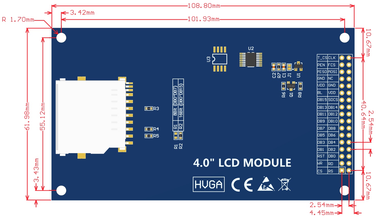
The red box in the above figure is the 8-bit/16-bit data bus mode switch, which is described as follows: | The red box in the above figure is the 8-bit/16-bit data bus mode switch, which is described as follows: | ||
: | |||
: | :Solder '''R2''' with 0Ω resistor or short circuit directly, and disconnect '''R1''': Select '''16'''-bit data bus mode (default),use '''DB0~DB15''' data pin | ||
:Solder '''R1''' with 0Ω resistor or short circuit directly, and disconnect '''R2''': Select '''8'''-bit data bus mode use '''DB0~DB7''' data pin | |||
{| class="wikitable" border="1" style="width: 650px; background-color: white;" | {| class="wikitable" border="1" style="width: 650px; background-color: white;" | ||
| Line 202: | Line 206: | ||
|- | |- | ||
|} | |} | ||
==<font color="blue">How to use on STM32 development board</font> == | ==<font color="blue">How to use on STM32 development board</font> == | ||
| Line 237: | Line 219: | ||
# Find the TFTLCD Slot on the development board, connect the module pins and Slot(For example, the module CS pin corresponds to the slot CS pin), | # Find the TFTLCD Slot on the development board, connect the module pins and Slot(For example, the module CS pin corresponds to the slot CS pin), | ||
::and then plug them directly into the Slot | ::and then plug them directly into the Slot | ||
| Line 246: | Line 229: | ||
# After the program is finished, observe the running status of the program. If it can be displayed normally, the program runs successfully. | # After the program is finished, observe the running status of the program. If it can be displayed normally, the program runs successfully. | ||
==<font color="blue">Program Download</font> == | |||
* [https://www.lcdwiki.com/res/Program/Parallel_Port/4.0inch/8_16BIT_ST7796S_MRB3951_V1.0/4.0inch_8&16BIT_Module_ST7796S_MRB3951_V1.0.zip '''4.0inch 16bit Parallel-Port Module package'''] | |||
==<font color="blue">Product Documentation</font> == | |||
* [https://www.lcdwiki.com/res/MRB3951/4.0inch_8&16BIT_Module_MRB3951_User_Manual_EN.pdf '''4.0inch 16bit Parallel-Port Module User Manual'''] | |||
* [https://www.lcdwiki.com/res/MRB3951/QD-40037C1-00_specification_V1.0.pdf '''4.0inch TFTLCD Specification'''] | |||
* [https://www.lcdwiki.com/res/MRB3951/4.0inch_MRB3951_Size.pdf '''4.0inch 16bit Parallel-Port Module Size Picture(pdf Version)'''] | |||
* [https://www.lcdwiki.com/images/7/7f/MRB3951-006.jpg '''4.0inch 16bit Parallel-Port Module Size Picture(jpg Version)'''] | |||
* [https://www.lcdwiki.com/res/MRB3951/4.0inch_MRB3951_Schematic_V1.0.pdf '''4.0inch 16bit Parallel-Port Module Schematic'''] | |||
* [https://www.lcdwiki.com/res/MRB3951/Altium_Package_library.zip '''4.0inch 16bit Parallel-Port Module LCD Schematic and PCB Package Library'''] | |||
* [https://www.lcdwiki.com/res/MRB3951/ST7796S-Sitronix.pdf '''Driver IC ST7796S Data sheet'''] | |||
==<font color="blue">Reference Materials</font> == | |||
* [https://www.lcdwiki.com/res/PublicFile/C51_Keil%26stc-isp_Use_Illustration_EN.pdf '''C51 Keil and stc-isp software use illustration'''] | |||
* [https://www.lcdwiki.com/res/PublicFile/STM32_Keil_Use_Illustration_EN.pdf '''STM32 keil software use illustration'''] | |||
* [https://www.lcdwiki.com/res/PublicFile/PCtoLCD2002_Use_Illustration_EN.pdf '''PCtoLCD2002 software use illustration'''] | |||
* [https://www.lcdwiki.com/res/PublicFile/Image2Lcd_Use_Illustration_EN.pdf '''Image2Lcd software use illustration'''] | |||
* [https://www.lcdwiki.com/Chinese_and_English_display_modulo_settings '''Chinese and English display modulo settings'''] | |||
==<font color="blue">Common Software</font> == | ==<font color="blue">Common Software</font> == | ||
Latest revision as of 14:44, 23 August 2025
Product Picture

Product Description
- 4.0-inch color screen, support 16BIT RGB 65K color display, display rich colors
- 320x480 resolution for clear display
- Supports 8-bit and 16-bit parallel bus transmission with fast transfer speed
- Supports ALIENTEK STM32 Mini, Elite, WarShip, Explorer, and Apollo development boards TFTLCD for direct plug-in use
- Support for touch function
- Support SD card function expansion
- Provides a rich sample program for STM32 and C51 platforms
- Military-grade process standards, long-term stable work
- Provide underlying driver technical support
Product Parameters
| Name | Parameter |
| Display Color | 16BIT RGB 65K color |
| SKU | MRB3951 |
| Screen Size | 4.0(inch) |
| Type | TFT |
| Driver IC | ST7796S |
| Resolution | 480*320 (Pixel) |
| Luminance | 260Cd/m2 |
| Module Interface | 8bit or 16Bit parallel interface |
| Active Area | 83.52x55.68(mm) |
| Module PCB Size | 61.98x108.80 (mm) |
| Operating Temperature | -20℃~60℃ |
| Storage Temperature | -30℃~70℃ |
| Operating Voltage | 3.3V~5V |
| Power Consumption | 0.51W |
| Rough Weight(Package containing) | 68 (g) |
Interface Definition

The red box in the above figure is the 8-bit/16-bit data bus mode switch, which is described as follows:
- Solder R2 with 0Ω resistor or short circuit directly, and disconnect R1: Select 16-bit data bus mode (default),use DB0~DB15 data pin
- Solder R1 with 0Ω resistor or short circuit directly, and disconnect R2: Select 8-bit data bus mode use DB0~DB7 data pin
| Number | Pin Label | Description |
| 1 | CS | LCD reset control pin( low level enable) |
| 2 | RS | LCD register / data selection control pin(high level: register, low level: data) |
| 3 | WR | LCD write control pin |
| 4 | RD | LCD read control pin |
| 5 | RST | LCD reset control pin( low level reset) |
| 6 | DB0 | LCD data bus low 8-bit pin |
| 7 | DB1 | |
| 8 | DB2 | |
| 9 | DB3 | |
| 10 | DB4 | |
| 11 | DB5 | |
| 12 | DB6 | |
| 13 | DB7 | |
| 14 | DB8 | LCD data bus high 8-bit pin (not used in 8-bit data bus mode) |
| 15 | DB9 | |
| 16 | DB10 | |
| 17 | DB11 | |
| 18 | DB12 | |
| 19 | DB13 | |
| 20 | DB14 | |
| 21 | DB15 | |
| 22 | SDCS | SD card selection control pin (used when using the SD card expansion function, this test program is not used) |
| 23 | BL | LCD backlight control pin(High level light) |
| 24 | VDD | Module power positive pin (module has integrated voltage regulator IC, so the power supply can be connected to 5V or 3.3V) |
| 25 | VDD | |
| 26 | GND | Module power ground pin |
| 27 | GND | |
| 28 | NC | LCD backlight power positive pin (default shared onboard backlight power supply, this pin can not be connected) |
| 29 | MISO | Touch screen SPI bus data input pin |
| 30 | MOSI | Touch screen SPI bus data output pin |
| 31 | PEN | Touch screen interrupt detection pin(Low level when a touch occurs) |
| 32 | FCS | Flash chip select control pin (used when using the Flash extension function, this test program is not used) |
| 33 | T_CS | Touch screen IC chip select control pin(Low level enable) |
| 34 | CLK | Touch screen SPI bus clock control pin |
How to use on STM32 development board
This module is compatible with the ALIENTEK STM32 development board. The specific usage is as follows:
- Step 1: Download the test program
- Download the STM32 test program from the Program Download column
- For a description of the relevant test procedures, please refer to the test program documentation in the package
- Step 2: Connect the STM32 development board
- Find the TFTLCD Slot on the development board, connect the module pins and Slot(For example, the module CS pin corresponds to the slot CS pin),
- and then plug them directly into the Slot
- Step 3: Compile and download the program to the development board
- Compile and download the program you need to test to the STM32 development board( Don't know how to compile and download?)
- Step 4: Observe the running of the program
- After the program is finished, observe the running status of the program. If it can be displayed normally, the program runs successfully.
Program Download
Product Documentation
- 4.0inch 16bit Parallel-Port Module User Manual
- 4.0inch TFTLCD Specification
- 4.0inch 16bit Parallel-Port Module Size Picture(pdf Version)
- 4.0inch 16bit Parallel-Port Module Size Picture(jpg Version)
- 4.0inch 16bit Parallel-Port Module Schematic
- 4.0inch 16bit Parallel-Port Module LCD Schematic and PCB Package Library
- Driver IC ST7796S Data sheet
Reference Materials
- C51 Keil and stc-isp software use illustration
- STM32 keil software use illustration
- PCtoLCD2002 software use illustration
- Image2Lcd software use illustration
- Chinese and English display modulo settings