More actions
No edit summary |
|||
| (5 intermediate revisions by 2 users not shown) | |||
| Line 5: | Line 5: | ||
en=https://www.lcdwiki.com/1.44inch_Arduino_SPI_Module_ST7735S_SKU:MAR1441 | en=https://www.lcdwiki.com/1.44inch_Arduino_SPI_Module_ST7735S_SKU:MAR1441 | ||
}} | }} | ||
== <font color="blue">Product Picture</font> == | == <font color="blue">Product Picture</font> == | ||
| Line 46: | Line 42: | ||
| align="center" |Resolution | | align="center" |Resolution | ||
| align="center" |128*128 (Pixel) | | align="center" |128*128 (Pixel) | ||
|- | |||
| align="center" |Luminance | |||
| align="center" |190 cd/m<sup>2</sup> | |||
|- | |- | ||
| align="center" |Module Interface | | align="center" |Module Interface | ||
| Line 60: | Line 59: | ||
|- | |- | ||
| align="center" |Operating Temperature | | align="center" |Operating Temperature | ||
| align="center" | - | | align="center" | -30℃~80℃ | ||
|- | |- | ||
| align="center" |Storage Temperature | | align="center" |Storage Temperature | ||
| align="center" | - | | align="center" | -30℃~80℃ | ||
|- | |- | ||
| align="center" |Operating Voltage | | align="center" |Operating Voltage | ||
| align="center" |5V/3.3V | | align="center" |5V/3.3V | ||
|- | |||
| align="center" |LED Current | |||
| align="center" |33.4(mA) | |||
|- | |- | ||
| align="center" |Power Consumption | | align="center" |Power Consumption | ||
| align="center" | | | align="center" |0.165 | ||
|- | |- | ||
| align="center" | | | align="center" |Rough Weight(Package containing) | ||
| align="center" | | | align="center" |12 (g) | ||
|} | |} | ||
| Line 130: | Line 132: | ||
|- | |- | ||
|} | |} | ||
==<font color="blue">Connect to Arduino</font> == | ==<font color="blue">Connect to Arduino</font> == | ||
| Line 189: | Line 181: | ||
==<font color="blue">Program Download</font> == | ==<font color="blue">Program Download</font> == | ||
* [https://www.lcdwiki.com/res/Program/Arduino_SPI/1.44inch/Arduino_SPI_ST7735S_MAR1441_V1.0/1.44inch_Arduino_SPI_Module_ST7735S_MAR1441_V1.0.zip '''1.44 inch Arduino SPI Module Package'''] | |||
==<font color="blue">Product Documentation</font> == | |||
* [https:// | * [https://www.lcdwiki.com/res/MAR1441/1.44inch_Arduino_SPI_Module_MAR1441_User_Manual_EN.pdf '''1.44 inch Arduino SPI Module User Manual'''] | ||
* [https://www.lcdwiki.com/images/4/46/1.44inch_MAR1441_Size.PNG '''1.44 inch Arduino SPI Module Size Picture'''] | |||
* [https://www.lcdwiki.com/res/MAR1441/QD14414B_specification_v1.1.pdf '''1.44 inch TFT Specifications'''] | |||
* [https://www.lcdwiki.com/res/MAR1441/1.44inch_MAR1441_schematic.pdf '''1.44 inch Arduino SPI Module Schematic'''] | |||
* [https://www.lcdwiki.com/res/MAR1441/1.44inch_SPI_LCD_schematic_package_14Pin.SchLib '''1.44 inch SPI LCD schematic package'''] | |||
* [https://www.lcdwiki.com/res/MAR1441/1.44inch_SPI_package_14pin_99SE.PcbLib '''1.44 inch SPI package'''] | |||
* [https://www.lcdwiki.com/res/MAR1441/ST7735S_V1.1_20111121.pdf '''Driver IC ST7735S Data sheet'''] | |||
==<font color="blue">Reference Materials</font> == | ==<font color="blue">Reference Materials</font> == | ||
Latest revision as of 16:06, 29 August 2025
Product Picture


Product Description
- 1.44-inch color screen,support 16BIT RGB 65K color display,display rich colors
- 128X128 resolution, clear display
- Using the SPI serial bus, it only takes a few IOs to illuminate the display
- With SD card slot for convenient function expansion
- Provide underlying libraries and rich sample programs for Arduino, C51, and STM32 platforms
- Military-grade process standards, long-term stable work
- Provide underlying driver technical support
Product Parameters
| Name | Parameter |
| Display Color | 16BIT RGB 65K color |
| SKU | MAR1441 |
| Screen Size | 1.44(inch) |
| Type | TFT |
| Driver IC | ST7735S |
| Resolution | 128*128 (Pixel) |
| Luminance | 190 cd/m2 |
| Module Interface | 4-wire SPI interface |
| Backlight | 1 White Led |
| Active Area | 26.2x27.2 (mm) |
| Module PCB Size | 31.49x43.95 (mm) |
| Operating Temperature | -30℃~80℃ |
| Storage Temperature | -30℃~80℃ |
| Operating Voltage | 5V/3.3V |
| LED Current | 33.4(mA) |
| Power Consumption | 0.165 |
| Rough Weight(Package containing) | 12 (g) |
Interface Definition

| Number | Pin Label | Description |
| 1 | VCC | LCD Power positive (3.3V~5V) |
| 2 | GND | LCD Power ground |
| 3 | GND | LCD Power ground |
| 4 | NC | Not defined, reserved |
| 5 | NC | Not defined, reserved |
| 6 | LED | Backlight control, high level lighting,
if not controlled, connect 3.3V always bright |
| 7 | CLK | LCD SPI bus clock signal |
| 8 | SDI | LCD SPI bus write data signal |
| 9 | RS | LCD register / data selection signal,
high level: register, low level: data |
| 10 | RST | LCD reset signal, low level reset |
| 11 | CS | LCD chip select signal, low level enable |
Connect to Arduino

|

|
|---|---|
| Arduino UNO direct insertion picture | Arduino Mega2560 direct insertion picture |
How to use on Arduino
- Step 1: Download the test program
- Download the Arduino test program from the Program Download column
- For a description of the relevant test procedures, please refer to the test program documentation in the package
- Step 2: Connect the Arduino development board
- Plug the module directly into the Arduino development board ( Do not plug in?)
- After the module is plugged in, power on the Arduino board
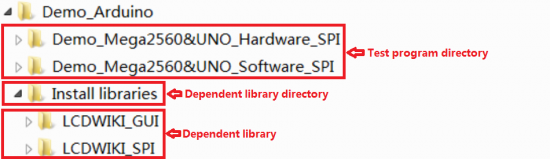
- Step 3: Copy the dependent library
- Make sure the Arduino IDE is installed on your computer (if it is not installed: Arduino IDE download URL)
- After installing the Arduino IDE, you need to copy the dependent library to the Arduino project directory as follows:
- (1) Decompress the downloaded test package
- (2) Copy the dependent libraries in the Install libraries directory in the package (shown below) to the libraries folder
- of the Arduino project directory ( Don't know the Arduino project directory?)

- Step 4: Compile and download the program to the development board
- Open the sample in the Example directory of the package to test, compile and download( Don't know how to compile and download?)
- Step 5: Observe the running of the program
- After the program is downloaded, run it directly and observe the running status. If it can be displayed normally, the program runs
- successfully, as shown in the following figure (take the colligate_test test program as an example):


Program Download
Product Documentation
- 1.44 inch Arduino SPI Module User Manual
- 1.44 inch Arduino SPI Module Size Picture
- 1.44 inch TFT Specifications
- 1.44 inch Arduino SPI Module Schematic
- 1.44 inch SPI LCD schematic package
- 1.44 inch SPI package
- Driver IC ST7735S Data sheet
Reference Materials
- Arduino IDE software use illustration
- C51 Keil and stc-isp software use illustration
- STM32 keil software use illustration
- PCtoLCD2002 software use illustration
- Image2Lcd software use illustration
- Chinese and English display modulo settings