More actions
No edit summary |
|||
| (20 intermediate revisions by 2 users not shown) | |||
| Line 6: | Line 6: | ||
}} | }} | ||
==<font color="blue"> | ==<font color="blue">Product Picture</font> == | ||
[[File:MSP1443-013.jpg|300px]][[File:MSP1443-008.jpg|300px]][[File:MSP1443-009.jpg|300px]] | [[File:MSP1443-013.jpg|300px]][[File:MSP1443-008.jpg|300px]][[File:MSP1443-009.jpg|300px]] | ||
==<font color="blue"> | ==<font color="blue">Product Description</font> == | ||
* 1. | * 1.44-inch color screen,support 65K color display,display rich colors | ||
* | * 128X128 resolution, clear display | ||
* | * Using the SPI serial bus, it only takes a few IOs to illuminate the display | ||
* | * Easy to expand the experiment with SD card slot | ||
* | * Provide a rich sample program | ||
* | * Military-grade process standards, long-term stable work | ||
* | * Provide underlying driver technical support | ||
==<font color="blue"> | ==<font color="blue">Product Parameters</font> == | ||
{| class="wikitable" border="1" style="width: 500px; background-color: white;" | {| class="wikitable" border="1" style="width: 500px; background-color: white;" | ||
| align="center" | | | align="center" |Name | ||
| align="center" | | | align="center" |Parameter | ||
|- | |- | ||
| align="center" | | | align="center" |Display Color | ||
| align="center" |RGB | | align="center" |RGB 65K color | ||
|- | |- | ||
| align="center" |SKU | | align="center" |SKU | ||
| align="center" |MSP1443 | | align="center" |MSP1443 | ||
|- | |- | ||
| align="center" | | | align="center" |Screen Size | ||
| align="center" |1.44(inch) | | align="center" |1.44(inch) | ||
|- | |- | ||
| align="center" | | | align="center" |Type | ||
| align="center" |TFT | | align="center" |TFT | ||
|- | |- | ||
| align="center" | | | align="center" |Driver IC | ||
| align="center" |ST7735S | | align="center" |ST7735S | ||
|- | |- | ||
| align="center" | | | align="center" |Resolution | ||
| align="center" |128*128 (Pixel) | | align="center" |128*128 (Pixel) | ||
|- | |- | ||
| align="center" | | | align="center" |Module Interface | ||
| align="center" |4-wire SPI interface | | align="center" |4-wire SPI interface | ||
|- | |- | ||
| align="center" | | | align="center" |Active Area (AA area) | ||
| align="center" |26.2x27.2(mm) | | align="center" |26.2x27.2(mm) | ||
|- | |- | ||
| align="center" | | | align="center" |Module PCB Size | ||
| align="center" |29.7x43.36(mm) | | align="center" |29.7x43.36(mm) | ||
|- | |- | ||
| align="center" | | | align="center" |Operating Temperature | ||
| align="center" | - | | align="center" | -20℃~60℃ | ||
|- | |- | ||
| align="center" | | | align="center" |Storage Temperature | ||
| align="center" | - | | align="center" | -30℃~70℃ | ||
|- | |- | ||
| align="center" | | | align="center" |VCC power voltage | ||
| align="center" |3.3V~5V | | align="center" |3.3V~5V | ||
|- | |- | ||
| align="center" | | | align="center" |Logic IO port voltage | ||
| align="center" |3.3V(TTL) | | align="center" |3.3V(TTL) | ||
|- | |- | ||
| align="center" | | | align="center" |Power Consumption | ||
| align="center" | | | align="center" |TBD | ||
|- | |- | ||
| align="center" | | | align="center" |Rough Weight(Package containing) | ||
| align="center" | | | align="center" |12 (g) | ||
|} | |} | ||
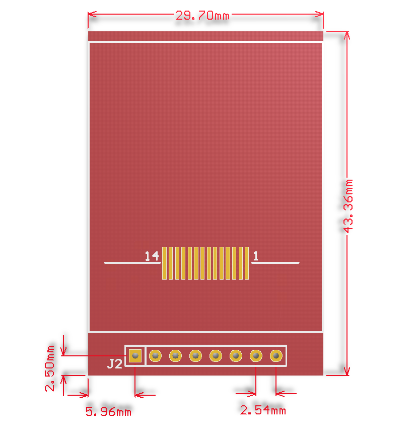
==<font color="blue"> | ==<font color="blue">Interface Definition</font> == | ||
[[File:MSP1443-014.jpg|500px]] | [[File:MSP1443-014.jpg|500px]] | ||
{| class="wikitable" border="1" style="width: | {| class="wikitable" border="1" style="width: 550px; background-color: white;" | ||
| align="center" | | | align="center" |Number | ||
| align="center" | | | align="center" |Pin Label | ||
| align="center" |Description | |||
|- | |- | ||
| align="center" |1 | |||
| align="center" |VCC | | align="center" |VCC | ||
|5V/3.3V power input | |||
|- | |- | ||
| align="center" |2 | |||
| align="center" |GND | | align="center" |GND | ||
| | |Ground | ||
|- | |- | ||
| align="center" |3 | |||
| align="center" |CS | | align="center" |CS | ||
| | |LCD chip select signal, low level enable | ||
|- | |- | ||
| align="center" |4 | |||
| align="center" |RESET | | align="center" |RESET | ||
| | |LCD reset signal, low level reset | ||
|- | |- | ||
| align="center" |5 | |||
| align="center" |A0 | | align="center" |A0 | ||
| | |LCD register / data selection signal, | ||
high level: register, low level: data | |||
|- | |- | ||
| align="center" |6 | |||
| align="center" |SDA | | align="center" |SDA | ||
| | |SPI bus write data signal | ||
|- | |- | ||
| align="center" |7 | |||
| align="center" |SCK | | align="center" |SCK | ||
| | |SPI bus clock signal | ||
|- | |- | ||
| align="center" |8 | |||
| align="center" |LED | | align="center" |LED | ||
| | |Backlight control, high level lighting, | ||
if not controlled, connect 3.3V always bright | |||
|- | |- | ||
|} | |} | ||
==<font color="blue"> | ==<font color="blue">Product Documentation</font> == | ||
* [https://www.lcdwiki.com/res/MSP1443/1. | * [https://www.lcdwiki.com/res/MSP1443/1.44inch_SPI_Module_MSP1443_User_Manual_EN.pdf '''1.44 inch SPI Module User Manual'''] | ||
* [https://www.lcdwiki.com/res/MSP1443/QD14414B_specification_v1.1.pdf '''1. | * [https://www.lcdwiki.com/res/MSP1443/QD14414B_specification_v1.1.pdf '''1.44 inch TFT Specifications'''] | ||
* [https://www.lcdwiki.com | * [https://www.lcdwiki.com/images/1/16/MSP1443-011.png '''1.44 inch SPI Module Size Picture'''] | ||
* [https://www.lcdwiki.com/res/MSP1443/MSP1443-1.4-SPI.pdf '''1. | * [https://www.lcdwiki.com/res/MSP1443/MSP1443-1.4-SPI.pdf '''1.44 inch SPI Module Schematic'''] | ||
* [https://www.lcdwiki.com/res/MSP1443/ST7735S_V1.1_20111121.pdf ''' | * [https://www.lcdwiki.com/res/MSP1443/Altium_1.44_14pin_QD14414B_Package_library.zip '''1.44 inch QD14414B TFT LCD Schematic and PCB Package Library'''] | ||
* [https://www.lcdwiki.com/res/MSP1443/ST7735S_V1.1_20111121.pdf '''Driver IC ST7735S Data sheet'''] | |||
==<font color="blue"> | ==<font color="blue">Program Download</font> == | ||
* [https://www.lcdwiki.com/res/Program/Common_SPI/1.44inch/SPI_ST7735_MSP1443_V1.1/1.44inch_SPI_Module_ST7735S_MSP1443_V1.1.zip '''1.44 inch SPI Module Package'''] | |||
==<font color="blue"> | ==<font color="blue">Reference Materials</font> == | ||
* [https://www.lcdwiki.com/res/PublicFile/ | * [https://www.lcdwiki.com/res/PublicFile/Arduino_IDE_Use_Illustration_EN.pdf '''Arduino IDE software use illustration'''] | ||
* [https://www.lcdwiki.com/res/PublicFile/C51_Keil%26stc- | * [https://www.lcdwiki.com/res/PublicFile/C51_Keil%26stc-isp_Use_Illustration_EN.pdf '''C51 Keil and stc-isp software use illustration'''] | ||
* [https://www.lcdwiki.com/res/PublicFile/ | * [https://www.lcdwiki.com/res/PublicFile/STM32_Keil_Use_Illustration_EN.pdf '''STM32 keil software use illustration'''] | ||
* [https://www.lcdwiki.com/res/PublicFile/ | * [https://www.lcdwiki.com/res/PublicFile/PCtoLCD2002_Use_Illustration_EN.pdf '''PCtoLCD2002 software use illustration'''] | ||
* [https://www.lcdwiki.com/res/PublicFile/ | * [https://www.lcdwiki.com/res/PublicFile/Image2Lcd_Use_Illustration_EN.pdf '''Image2Lcd software use illustration'''] | ||
* [https://www.lcdwiki.com/Chinese_and_English_display_modulo_settings '''Chinese and English display modulo settings'''] | |||
== <font color="blue"> | == <font color="blue">Applications</font> == | ||
* | * Example of connecting to the ArduinoD1 Mini application: | ||
'''[[【Application】1.44inch SPI Module MSP1443 with D1 mini]]''' | '''[[【Application】1.44inch SPI Module MSP1443 with D1 mini]]''' | ||
==<font color="blue"> | ==<font color="blue">Common Software</font> == | ||
* [https://www.lcdwiki.com/res/software/PCtoLCD2002.zip '''PCtoLCD2002'''] | * [https://www.lcdwiki.com/res/software/PCtoLCD2002.zip '''PCtoLCD2002'''] | ||
Latest revision as of 10:43, 9 November 2019
Product Picture


Product Description
- 1.44-inch color screen,support 65K color display,display rich colors
- 128X128 resolution, clear display
- Using the SPI serial bus, it only takes a few IOs to illuminate the display
- Easy to expand the experiment with SD card slot
- Provide a rich sample program
- Military-grade process standards, long-term stable work
- Provide underlying driver technical support
Product Parameters
| Name | Parameter |
| Display Color | RGB 65K color |
| SKU | MSP1443 |
| Screen Size | 1.44(inch) |
| Type | TFT |
| Driver IC | ST7735S |
| Resolution | 128*128 (Pixel) |
| Module Interface | 4-wire SPI interface |
| Active Area (AA area) | 26.2x27.2(mm) |
| Module PCB Size | 29.7x43.36(mm) |
| Operating Temperature | -20℃~60℃ |
| Storage Temperature | -30℃~70℃ |
| VCC power voltage | 3.3V~5V |
| Logic IO port voltage | 3.3V(TTL) |
| Power Consumption | TBD |
| Rough Weight(Package containing) | 12 (g) |
Interface Definition

| Number | Pin Label | Description |
| 1 | VCC | 5V/3.3V power input |
| 2 | GND | Ground |
| 3 | CS | LCD chip select signal, low level enable |
| 4 | RESET | LCD reset signal, low level reset |
| 5 | A0 | LCD register / data selection signal,
high level: register, low level: data |
| 6 | SDA | SPI bus write data signal |
| 7 | SCK | SPI bus clock signal |
| 8 | LED | Backlight control, high level lighting,
if not controlled, connect 3.3V always bright |
Product Documentation
- 1.44 inch SPI Module User Manual
- 1.44 inch TFT Specifications
- 1.44 inch SPI Module Size Picture
- 1.44 inch SPI Module Schematic
- 1.44 inch QD14414B TFT LCD Schematic and PCB Package Library
- Driver IC ST7735S Data sheet
Program Download
Reference Materials
- Arduino IDE software use illustration
- C51 Keil and stc-isp software use illustration
- STM32 keil software use illustration
- PCtoLCD2002 software use illustration
- Image2Lcd software use illustration
- Chinese and English display modulo settings
Applications
- Example of connecting to the ArduinoD1 Mini application:
【Application】1.44inch SPI Module MSP1443 with D1 mini