Difference between revisions of "0.96inch OLED Module (IIC-4P SKU:MC096VX)"
(→Using Instructions) |
(→Using Instructions) |
||
| Line 243: | Line 243: | ||
SDA: data signal of IIC bus | SDA: data signal of IIC bus | ||
| + | |||
| + | The VCC is connected to 5V power supply pin of the one-chip computer,the GND is connected to GND pin, | ||
| + | |||
| + | the SCL and the SDA need to be wired according to different platform pin definition. | ||
| + | |||
| + | The C51 and STM32 typically use analog IIC by defining their own two pins as SCL and SDA. | ||
| + | |||
| + | The Arduino uses the hardware IIC,that is,the chip already defines the SCL and SDA pins.We do not need to redefine. | ||
| + | |||
| + | Once connected to the line, you can run the test program which we provided for testing. | ||
==<font color="blue">Driver download</font> == | ==<font color="blue">Driver download</font> == | ||
Revision as of 10:25, 13 June 2018
Contents
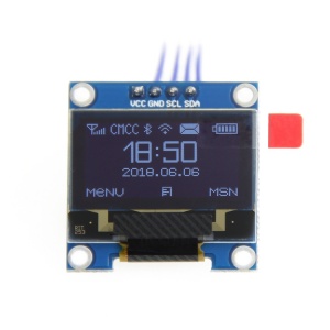
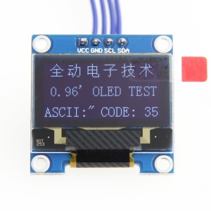
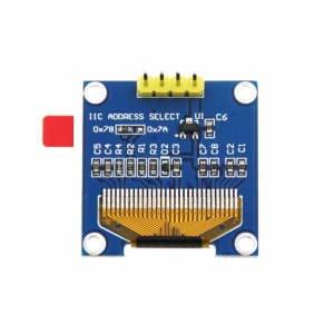
Product picture
Product description
- High resolution: 128x64 (have the same resolution as 12864, high PPI)
- Large viewing angle: greater than 160° (a screen with the largest viewing angle in the monitor)
- Ultra-low power consumption: it's 0.06w in normal condition(far less than TFT display)
- Wide voltage supply (3V~5V), 3.3V and 5V level logic compatible, no level shifter IC
- IIC interface and only requires 2 IOs to light up easily
- The range of working temperature is industrial (-20°C~70°C)
- Military-grade process standards, long-term work steadily
- Provide rich multi-platform routines and the technology support of underlying driver
- Have three color display schemes of yellow and blue,white,blue to choose from
Product parameters
| name | color category | ||
| display color | white | blue | Blue and yellow |
| SKU | MC096VW | MC096VB | MC096VY |
| size | 0.96(inch) | ||
| type | OLED | ||
| OLED driver chip | SSD1306 | ||
| resolution | 128*64 (Pixel) | ||
| Module interface | IIC,4PIN | ||
| Effective display area | 21.744x10.864(mm) | ||
| Module size | 27.3x27.8(mm) | ||
| Field of View | >160° | ||
| Working temperature | -20℃~70℃ | ||
| storage temperature | -30℃~80℃ | ||
| Working voltage | 3.3V / 5V | ||
| power dissipation | Full on is about 25mA,Full off is about 1.5mA。 | ||
| product weight | 15(g) | ||
Interface definition
| PIN | label | Pin description |
| 1 | VCC | OLED positive pole of power(3.3V~5V) |
| 2 | GND | OLED GND of power |
| 3 | SCL | OLED clock signal of IIC bus |
| 4 | SDA | OLED data signal of IIC bus |
Product size
Product size drawing:0.96 inch OLED Product size drawing
Hardware description
Hardware schematic:QD electronic 0.96 inch OLED display module hardware schematic.pdf
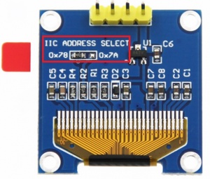
IIC hardware adjustment instructions of device address to slave device:
As the picture shows,in the red rectangle,if the resistor is connected to 0x78,
it indicates that the IIC slave address is 0x78,if the resistor is connected to 0x7A,
it indicates that the IIC slave address is 0x7A.
Software description
This module provides testing programs for three platforms,namely, C51, STM32, and Arduino,
The test program for each platform consists of roughly three parts:Platform related code,
OLED operation related code, and IIC operation related code.With the exception of platform-related
code that varies from platform to platform, the other two parts of the code are similar in principle
and implementation, and have nothing to do with the platform used.On the same platform,
the code can be ported directly, just by modifying the relevant pin definitions to work properly.
C51 code description
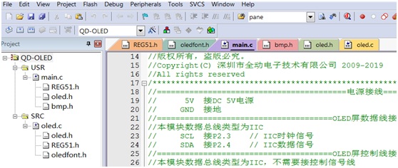
Open the C51 code project and find the following file:
REG51. H is platform-related code that defines some platform-related parameters.
Oledfont.h and bmp.h store pictures and Chinese characters after taking the lattice array.
Oled.h stores some of the parameters associated with OLEDs, including pin definitions.
Oled.c stores some functions related to OLED screen operations, including IIC read and write, OLED screen data writing, etc.
Main.c is the main program operation.
As we can see from the above description, we just need to modify the pin definition in the oled.h file.
Open the oled.h file and find the following:
Just modify the values of OLED_SCL and OLED_SDIN on it.
In this modules,the P23 pin is defined as the clock signal pin, and the P24 pin is defined as the data signal pin.
Find the following content, you can modify the IIC slave address:
The IIC address of this OLED module is 0x78.
STM32 code description
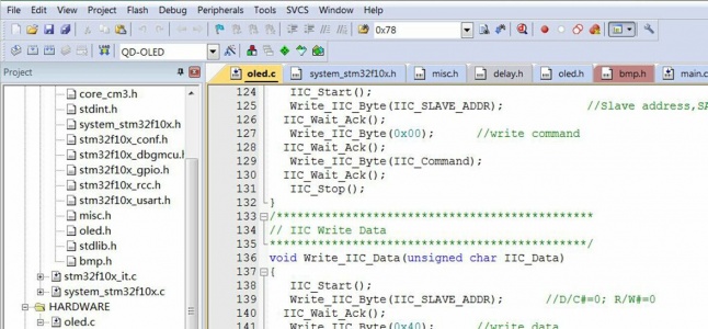
Open the STM32 code project and find the following file:
In addition to main.c, oled.c, oled.h, bmp.h, oledfont.h, the other is platform-specific code.
Oledfont.h and bmp.h store pictures and Chinese characters after taking the lattice array.
Oled.h stores some of the parameters associated with OLEDs, including pin definitions.
Oled.c stores some functions related to OLED screen operations, including IIC read and write, OLED screen data writing, etc.
Main.c is the main program operation.
Since the STM32 is more GPIO port initialization operation than C51,the migration code needs to modify both the oled.h and oled.c files.
Open the oled.h file and find the following:
According to your own definition,modify the GPIO group and pin of GPIO_ResetBits and GPIO_SetBits.
In this modules, the pin 13 of GPIOB is defined as the clock signal pin, and the pin 14 of GPIOB is defined as the data signal pin.
Find the following content, you can modify the IIC slave address:
The IIC address of this OLED module is 0x78.
Open the oled.c file and find the following:
The output mode,rate,and setting of the pin are set separately.
Arduino code description
The Arduino uses hardware IIC. the IIC pins have been defined inside the chip,so there is no need to define IIC in software.
It is only that different types of microcontrollers have different definitions of IIC which need to be adjusted on the wiring.
Since the software uses the U8glib open source library, when initializing,
you need to select the correct class based on the type of OLED screen driver IC.
For example, this module uses U8GLIB_SSD1306_128X64 u8g (U8G_I2C_OPT_NONE) for initialization.
If you want to modify the IIC slave device address, you need to open the u8g_com_arduino_ssd_i2c.c file and find the following:
The IIC address of this OLED module is 0x3c*2(0x78).
Using Instructions
The data manual of SSD1306 shows that the IC supports the four-wire and three-wire SPI,IIC interface and the parallel port connection of 8bit.
Because the parallel port connection mode occupies more data lines,wiring trouble,so it is not commonly used.
How to choose the communication interface mode,this is configured by the three pins of BS0,BS1 and BS2.
The specific definition is as shown below:
This module uses the IIC communication interface,only need to connect 4 lines to complete the OLED screen data communication,
as shown in the following figure:
VCC: positive pole of power(connect to 5V power)
GND: negative pole of power(connect to ground)
SCL: clock signal of IIC bus
SDA: data signal of IIC bus
The VCC is connected to 5V power supply pin of the one-chip computer,the GND is connected to GND pin,
the SCL and the SDA need to be wired according to different platform pin definition.
The C51 and STM32 typically use analog IIC by defining their own two pins as SCL and SDA.
The Arduino uses the hardware IIC,that is,the chip already defines the SCL and SDA pins.We do not need to redefine.
Once connected to the line, you can run the test program which we provided for testing.
Driver download
baiduyun download:0.96 inch OLED display module data of QD electronic V1.0
Common software description
the software description is in the software package and the download address as follows:
PCtoLCD2002:PCtoLCD2002
