Difference between revisions of "【Application】1.44inch SPI Module MSP1443 with D1 mini"
(Created page with "{{lan | cn=http://www.lcdwiki.com/zh/【Application】1.44inch_SPI_Module_MSP1443_with_D1_mini | en=http://www.lcdwiki.com/【Application】1.44inch_SPI_Module_MSP14...") |
(→Wiring Description) (Tag: Visual edit) |
||
| Line 21: | Line 21: | ||
| align="center" |1 | | align="center" |1 | ||
| style="width: 80px" align="center" |LED | | style="width: 80px" align="center" |LED | ||
| − | | align="center" | | + | | align="center" |3.3V |
| − | |LCD backlight control pin( | + | |LCD backlight control pin( connect to 3.3V) |
|- | |- | ||
| align="center" |2 | | align="center" |2 | ||
Revision as of 10:27, 11 November 2019
Contents
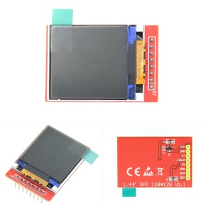
Product Picture
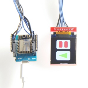
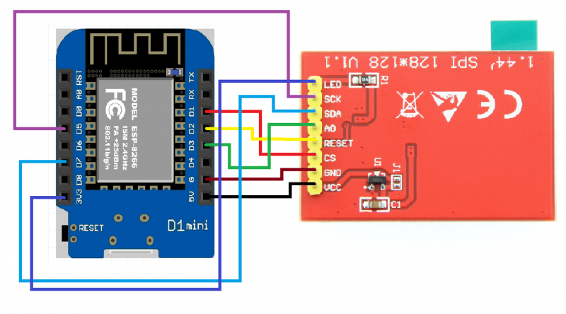
Wiring Description
| NUMBER | PIN | D1 miniDevelopment board corresponding wiring pin | 引脚说明 |
| 1 | LED | 3.3V | LCD backlight control pin( connect to 3.3V) |
| 2 | SCK | D5 | LCD SPI bus clock pin |
| 3 | SDA | D7 | LCD SPI bus write data pin |
| 4 | A0/DC | D3 | LCD register / data selection control pin |
| 5 | RESET | D2 | LCD reset control pin |
| 6 | CS | D1 | LCD chip selection control pin |
| 7 | GND | G | Power ground |
| 8 | VCC | 5V | Power positive |
